Site Preparation Manual
Field Services - Technical Manuals
INDEX
Introduction
Example Layouts For Optimal Design
Feed Intake Specifications
IPW Technology Specifications
IPW Technology Specifications | 2-Position
IPW Technology Specifications | 2-Position – One Side
IPW Technology Specifications | 4-Position
IPW Technology Specifications | 6-Position
Electrical Specifications
Data Hub Line of Sight
INTRODUCTION
Vytelle SENSE™ is our proprietary individual animal data capture system. It records feed intake and in-pen weight gain measurements to help you identify elite-performing animals expressing economically and environmentally important traits.
The Site Preparation Guide outlines the essential details needed when considering and preparing for Vytelle SENSE technology for your operation. It provides information regarding the Vytelle SENSE Feed Intake and In-Pen Weighing technology, example pen layouts, pen requirements for electrical and concrete along with water troughs dimensions to be used with IPW. Included is guidance on understanding potential Radio Frequency (RF) interference and how to assess and mitigate any issues found.
Once you have decided to proceed, Vytelle will work with you to build customized drawings based on your site specifics and monitoring goals. The Vytelle SENSE team will be with you each step of the way to ensure your site is prepared prior to the installation date according to specification for a successful and seamless implementation.
EXAMPLE LAYOUTS FOR OPTIMAL DESIGN
Two-Pen Configuration
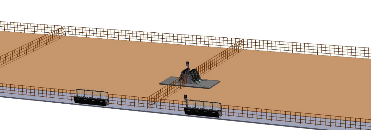
• Eight Feed Intake nodes, four nodes per pen
• One 4-position IPW, two positions per pen
• Configuration: nodes are split into two pens with the IPW unit on a shared fence line
Four Pen Configuration
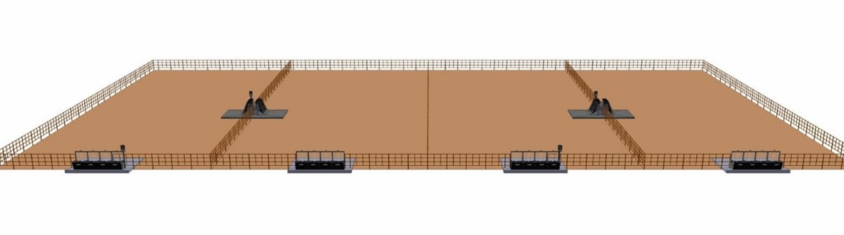
• Sixteen Feed Intake nodes, four nodes per pen
• Two 4-position IPW, two positions per pen
• Configuration: nodes are split into four pens with the IPW units on shared fence line
Two Pen Configuration
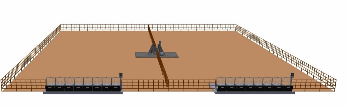
• Sixteen Feed Intake nodes, eight nodes per pen
• One 4-position IPW, two positions per pen
• Configuration: nodes are split into two pens with the IPW unit on a shared fence line
TECHNOLOGY GUIDELINES
• Vytelle SENSE technology is made for a production environment and doesn’t require a roof
• Recommended Feed Intake capacity is 8 bulls to 1 node or 10 heifers to 1 node
• Recommended IPW capacity is 50 animals to 1 IPW position
• Recommended minimum of two IPW positions/pen
• Recommended pen density is applicable to welfare guidelines and can vary depending on the site environment, management practices, indoor vs. outdoor design and national/local regulations. Typically, the range is from 300 sq. ft./91.44 sq. m per animal to 50 sq. ft./15.24 sq. m per animal.
FEED INTAKE SPECIFICATIONS
Feed Intake Node Specifications
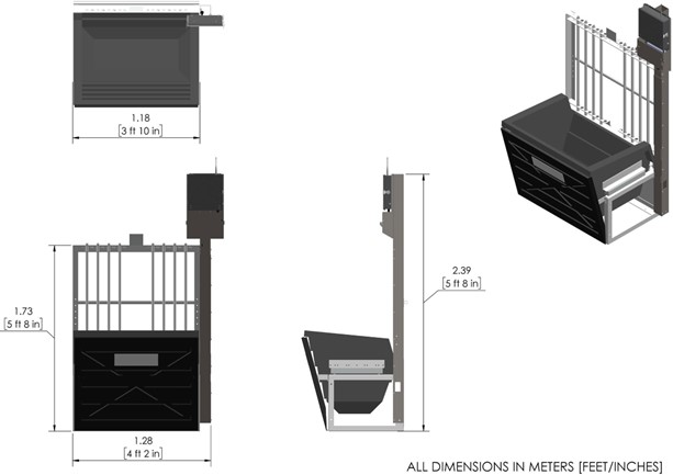
Eight Feed Intake Nodes
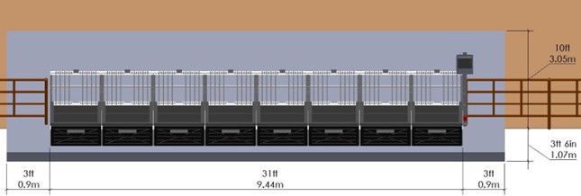
Up to 8 nodes can be connected to one Vytelle DAQ panel. If the nodes are split into two pens, the maximum distance for the furthest feed intake node from the DAQ panel including the panel post is 80 feet (24.4m).
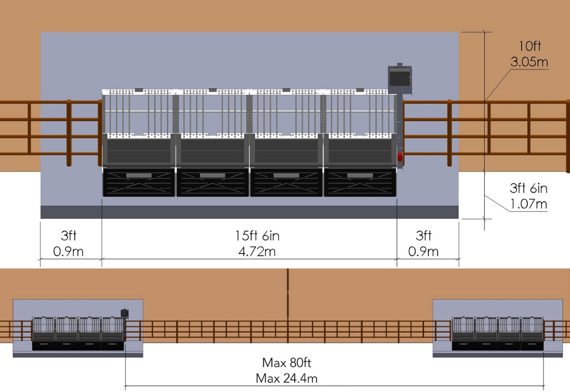
Four Feed Intake Nodes
Feed Intake Concrete Pad Cross Section
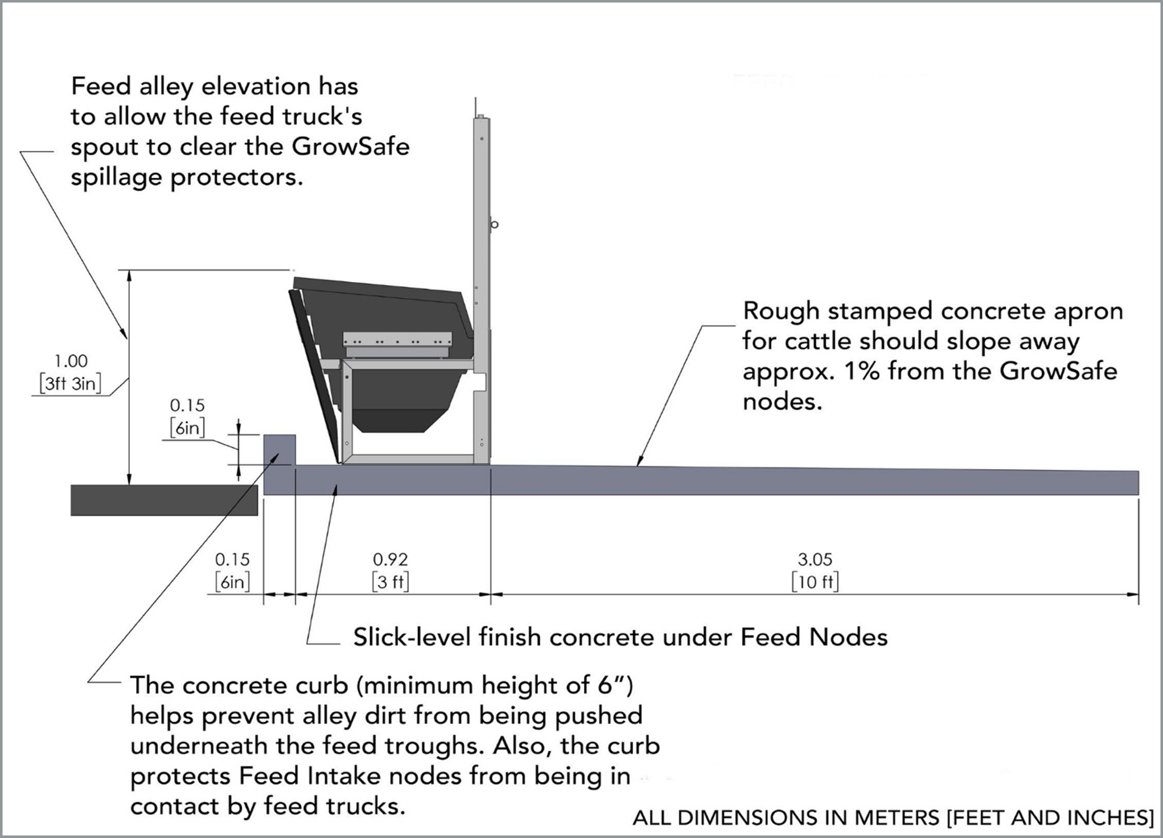
• The Feed Intake node requires specific cement specifications
• The grated concrete apron should slope approximately 1% away from the nodes where the cattle stand
• The concrete curb helps to prevent gravel or dirt from alley from being pushed under the feed troughs
• Ensure all feed trucks/wagons have a 40-inch/1.016m high discharge spout
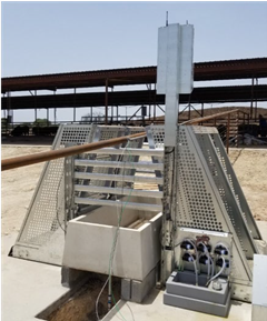
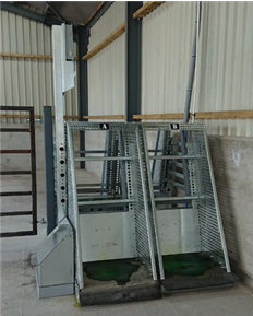
IPW TECHNOLOGY SPECIFICATIONS
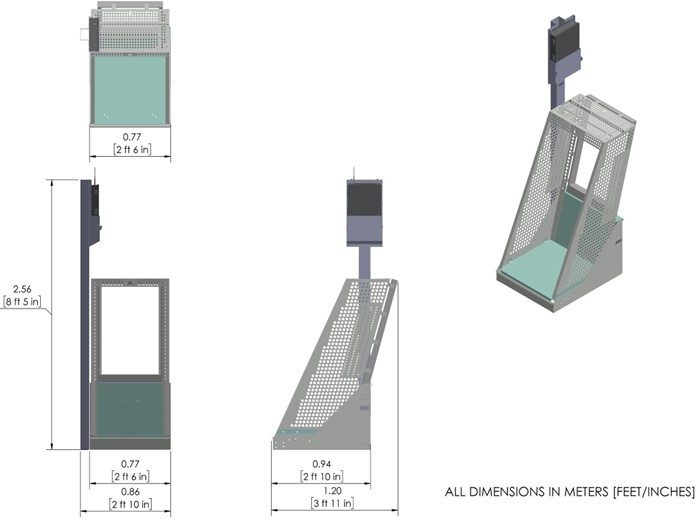
IPW Position Specifications
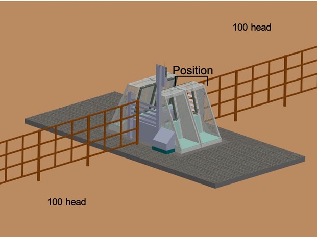
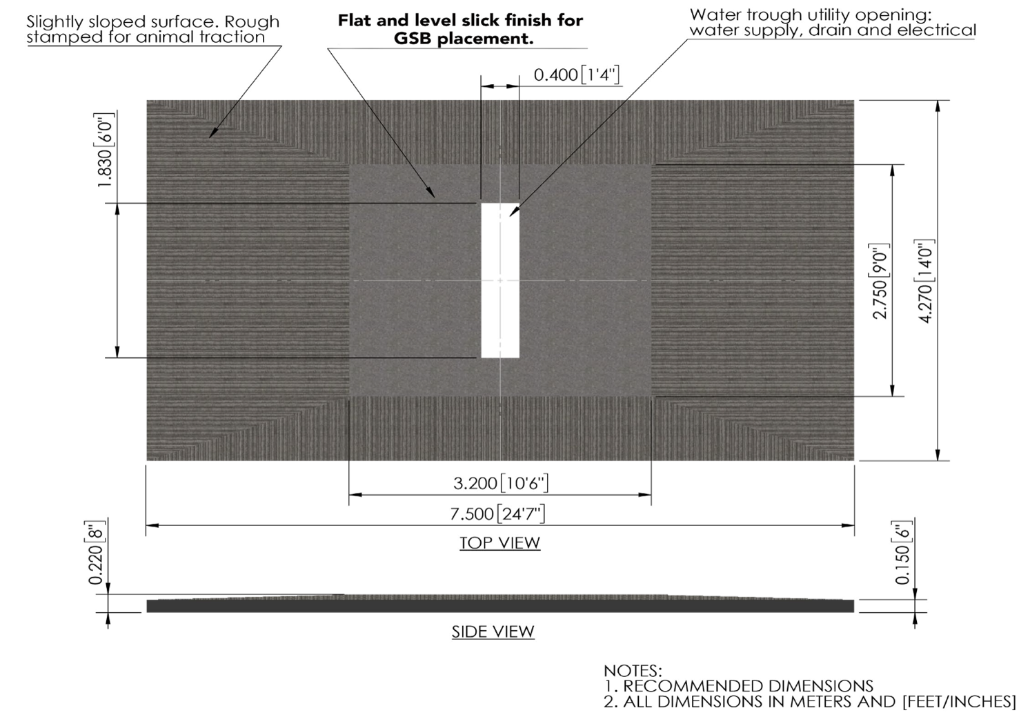
IPW TECHNOLOGY SPECIFICATIONS - 2 - POSITION
IPW 2 Position Specifications
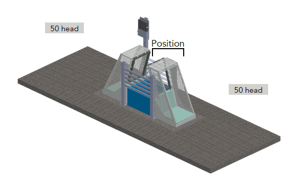
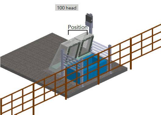
• 2-position IPW capacity; 100 head of cattle, 50 animals per position
• Place the IPW on level, slick-finished concrete for the base to be level
• The grated apron should slope away from the IPW for proper drainage
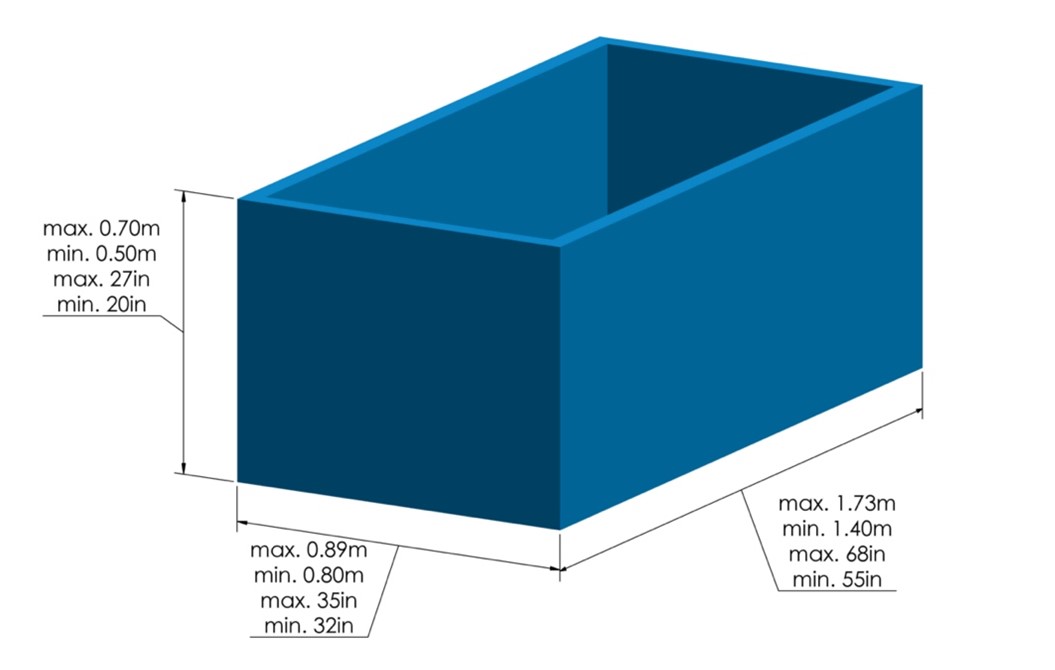
2-Position IPW – Water Trough Dimensions
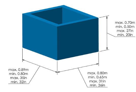
• Required maximum/minimum trough dimensions to be compatible with the 2-position IPW
• These dimensions are compatible with a standard Johnson J360 water tank
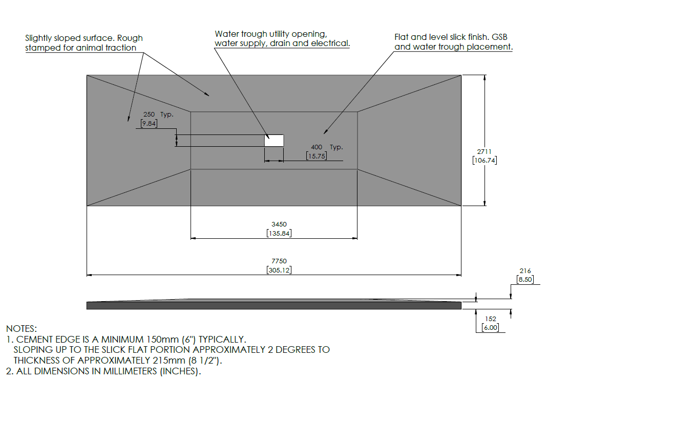
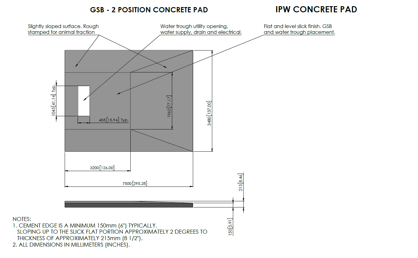
2-Position IPW – Cement
IPW TECHNOLOGY SPECIFICATIONS - 2 - POSITION, ONE SIDE
IPW Position Specifications
• 2-position IPW capacity; 100 head of cattle, 50 animals per position
• Place the IPW on level, slick-finished concrete for the base to be level
• The grated apron should slope away from the IPW for proper drainage
2-Position IPW – Water Trough Dimensions
• Required maximum/minimum trough dimensions to be compatible with the 2-position IPW, one side.
• These dimensions are compatible with a standard Johnson J720 water tank
2-Position IPW, one side – Cement
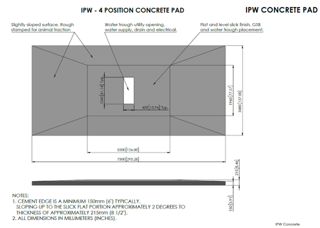
IPW TECHNOLOGY SPECIFICATIONS - 4 - POSITION
IPW Position Specifications
• 4-position IPW capacity; 200 head of cattle, 50 animals per position
• Place the IPW on level, slick-finished concrete for the base to be level
• The grated apron should slope away from the IPW for proper drainage
4-Position IPW – Water Trough Dimensions
• Required maximum/minimum trough dimensions to be compatible with the 4-position IPW
• These dimensions are compatible with a standard Johnson J720 water tank
4-Position IPW – Cement
IPW TECHNOLOGY SPECIFICATIONS - 6 - POSITION
6-Position IPW – Cement
ELECTRICAL SPECIFICATIONS
Electrical Guidance
The purpose of this section is to provide electrical installation requirements. Electrical installation will be conducted prior to the installation of the Vytelle SENSE system, and prior to a Vytelle Technician arriving onsite.
The following regulations and recommendations specify standards which are aimed at the protection and proper function of the Vytelle SENSE system. In addition, the regulations specify power quality and supply continuity requirements. The Vytelle 8000 system uses a variable voltage supply: 100V to 240V, 4 Amps or single phase.
CONDITION
Proper placement of electrical prior to the installation of the Vytelle SENSE system will help ensure that installation of the Vytelle SENSE system be conducted smoothly and precisely.
When installing electrical for the Vytelle SENSE system ensure to adhere to the following considerations:
• Dedicated electrical source
• Proper placement
• Proximity to radio frequency (RF) equipment
• Outlet height requirements
• Cable insulation
• Cable conduit
DEDICATED ELECTRICAL SOURCE
A dedicated electrical source must be used to power the Vytelle SENSE system. This will prevent any RF interference that could be caused by other equipment. DO NOT connect other equipment, even temporarily, to the same power source. Failure to do so can result in failed data during a trial.
Examples of equipment that should not be connected to the same power source, but is not limited to:
• Variable speed motors
• Supplement bins
• Welders
• Water pumps
PROXIMITY TO RF EQUIPMENT
Due to issues with RF interference it is important that the Vytelle SENSE system be located away from equipment that transmits or has RF emission. If the Vytelle SENSE system is located near equipment that transmits or has RF emissions this can disrupt the data signals that the Vytelle SENSE system is collecting. This can lead to adverse effects, for example, intermittent connectivity loss, poor throughput, and low data rates. If RF interference is a concern please contact Vytelle for additional information or guidance.
DAQ ELECTRICAL PLACEMENT CONSIDERATIONS
On a typical Vytelle SENSE system the DAQ Panel is mounted on a DAQ Panel Post as seen in Figure 1. Mounting to a building structure as shown in Figure 2 is also an option. The electrical outlet must be able to reach the DAQ Panel at the highest point of the DAQ Panel Post.
RECOMMENDED CONDUIT HEIGHT DIMENSION
Vytelle recommends that the electrical conduit be installed at nine-feet (2750mm) to accommodate for the DAQ Panel height requirement. The conduit can be adjusted to the actual required length at the time of installation.
CABLE INSULATION / POWER REQUIREMENTS
Electrical cabling must be protected with shielded insulated conductors. Shielding reduces electrical noise and reduces its impact on signal. Shielding prevents crosstalk between cables located near each other. Power cables are to be electromagnetic compatible to minimize noise generation, which could affect radio and data communication.
CONDUIT REQUIREMENTS
Vytelle requires that wiring be installed in a shielded conduit. A minimum of 50mm PVC is recommended. Stray voltage, current and high frequency noise can damage circuits. This could interrupt the performance of the Vytelle SENSE system. Shielded conduit provides a significant solution to this potential problem.
Ensure that the conduit that is utilized is rated for the intended use (e.g. exterior use, underground use, or wet location use).
WATER TROUGH CONSIDERATIONS
When installing the electrical conduit and cabling at the Vytelle Beef system, extra precaution needs to be adhered to ensure the conduit does not become a hazard for the animals.
BELOW GROUND ELECTRICAL
If cabling is being installed below ground. It is recommended the conduit be installed under the trough or adjacent to the trough, as seen in Figure 3.
ABOVE GROUND ELECTRICAL
If above ground cabling is being utilized (e.g. a closed facility) ensure the conduit is installed directly above the system as seen in Figure 4.
DATA HUB LINE OF SIGHT
CHOOSING AN APROPRIET DATA HUB LOCATION
The success of wireless communication between the DAQ panels and the Data hub depend on the environment in which communication occurs. The effective transmission of data between the Vytelle SENSE equipment in the pens and the Data hub via wireless radio communication requires that the best conditions are met.
When choosing a location for the Data hub, in addition of the need to use
the correct antenna with the intended application characteristics, it is
essential to analyze the physical environment between the antennae.
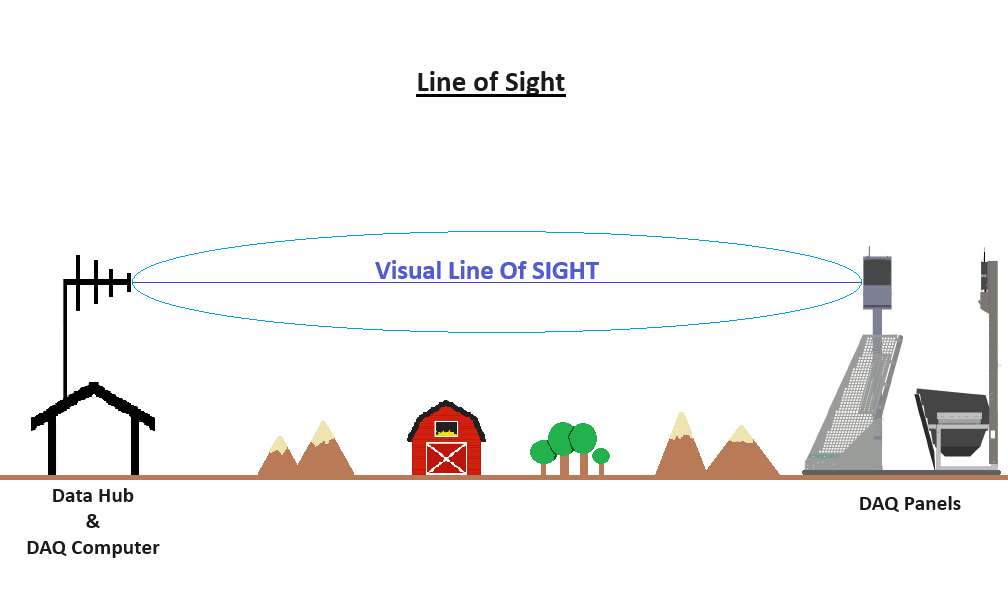
Refers to the line of clear & unobstructed sight between two points.
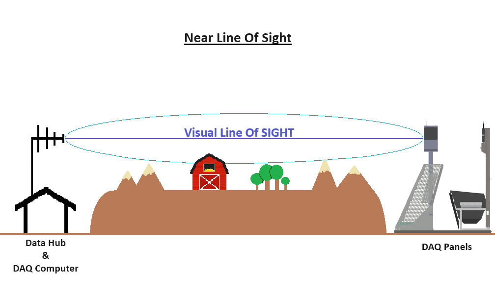
The degree of interference in communication increases as the obstruction approaches to
the closest area from the visual field. In this scenario, there is a physical barrier that partially blocks the edge of the line of sight. The maximum distance between the DAQ panels and Data hub will be affected by these obstructions. Be aware of growing trees or other obstructions that could obscure the clear line of sight over time.
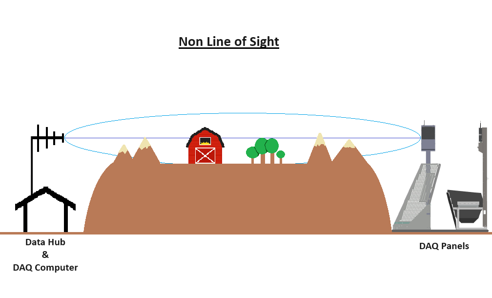
In this scenario, the field of view between the DAQ panels and the Data hub does not exist. The Vytelle SENSE equipment will NOT be able to collect data in this scenario. the data hub and system computer will have to be relocated to a location that had a clear line of sight to the equipment.
TECHNICAL SUPPORT
If you have any further questions please contact Vytelle SENSE Technical Support at support@vytelle.com or by calling toll-free from US & Canada: 1-866-689-3477 ext. 1 The team is available Monday to Friday 7:00am to 5:00pm MST (excluding Canadian Statutory Holidays). After hours, please leave a detailed voicemail, email, or trial note and a TSR will respond the next business days.
Optimized for print with Google Chrome browser.
Lorem ipsum dolor sit amet, consectetur adipiscing elit. Ut elit tellus, luctus nec ullamcorper mattis, pulvinar dapibus leo.