8000 Vytelle SENSE System Training Manual
Field Service - Technical Manuals
This training guide describes the operation, use, and purpose of the Feed Intake and In-Pen Weighing systems IPW and their components.
SYSTEM OVERVIEW
Feed Intake
The Vytelle SENSE™ solution utilizes Feed Intake Nodes which are a feed weighing system that can be used in conjunction with the In-Pen Weighing Positions to provide a more accurate depiction of individual animal efficiency. The system replaces the traditional feed bunk with a set of individual scale-mounted feed troughs to enable measurement of individual animal consumption. The Feed Intake Nodes require cattle to lower their heads into the feed trough to collect their RFID information as they eat. At this point, the trough scale records a feeding event collects a weight reading of how much feed is in the bunk at the start of the feeding event. This number is compared to the scale reading when the feeding event is over (i.e., animal’s head is no longer in the bunk) and the difference is attributed to that animal’s consumption. Feed Intake Nodes are installed to fit the existing pen layout at a customer site. Feed Intake Nodes can be installed singly, in pairs, or in larger blocks. An individual DAQ panel can support a maximum of eight nodes.
FEED INTAKE DEFINITIONS
Explain the system components starting roughly in order of troubleshooting. Depending on the issue being experienced, weight or tag reading issue, you always want to work back from the component furthest out from the DAQ panel. i.e., for a tag reading issue, you would work from the antenna (first component in the line of reading tags) back through the Pigtail connections, the RTU, the Data cable, and lastly the DAQ panel. For a weight issue you would start at the trough, working back to the pigtail, the RTU, the Data cable, and ending at the DAQ panel.
FEED INTAKE HARDWARE
• Wind deflector – helps to prevent wind buffeting of the bunk in outdoor environments, which reduces vibration or “noise” (show install and removal).
• Spill deflector – usually installed between adjacent troughs. Helps to prevent feed from accumulating on or near the RTU load bars and gives some protection from the elements (show install, removal & point out adjustment).
• Trough – (show install removal & dumping technique) grey injection moulded plastic feed trough that contains the antenna used to read the EID tag of the animal feeding. Has metal brackets that position the trough on the RTU load bars (scales). UNPLUG PIGTAIL BEFORE REMOVAL!
a. The customer must locate where to look/ feel for a correctly seated trough (load bar sitting correctly in the groves on the trough).
b. THE CUSTOMER AND OR PERSON DEALING WITH THE SYSTEM MUST REPLICATE REMOVAL AND INSTALLATION!
c. Holds approx. 400lbs – 180kg depending on ration density. Trough will go into error over 500lbs.
d. Very durable.
e. Can be rewired (remove foam & reinstall 30ft 14AWG stranded wire mentioned earlier).
f. Shouldn’t have anything rubbing on bunk when in position or it will negatively affect the weight reading.
g. Always test the trough with the test wand after any service or cleaning is preformed to make sure you still have good read range.
• RFID antenna – two complete wraps (not twisted pair) 14AWG stranded antenna wire that is secured in the upper lip of the trough which reads RFID tag numbers as animals lower their heads into the trough to feed. Secured in trough with foam backing rod.
a. If replacing antenna wire, the butt connector that is factory installed is not necessary when replacing the wire. It is part of the procedure used at the factory to expedite the install. Having the complete two wraps around the trough lip is the most critical part of the antenna wire replacement.
b. When crimping new Spade connectors onto the antenna wire ensure that the insulation is not pinched in between the connector and copper wire as this could impede the antennas functionality.
• Pigtail – connects the RFID antenna in the trough to the RTU box. Located on the side of the trough under a black plastic cover that is secured with a wing nut. (Show installation and removal)
a. Must make sure pigtail is disconnected before the bunk is removed from the frame (we provide extras because it does happen from time to time).
b. Make sure cam-lock connector is fully engaged.
c. Show spade connectors, replacement method, orientation or placement of the spade connectors doesn’t matter.
d. Talk about pigtail extension & how to use when troubleshooting EID tag reading issues in troughs full of food.
• RTU – the scale that does the weighing of feed. Consists of an RTU box and four load cells; two load cells per bar; two bars per set. Also transmits RFID data to the DAQ panel. (Pinpoint hardware locations and understand replacement)
a. RTU box – the device that collects the RFID data from the antenna and weight information from the load cells in the load bars.
b. RFID antenna port – connection point for the RFID antenna.
c. Data cable port – connection point for the data cable.
d. Long bar – the bar attached to the RTU box that has longer cabling.
e. Short bar – the bar attached to the RTU box that has shorter cabling.
• RTU spacers – urethane mounts that support the RTU bars on the frame. These spacers aid in minimizing the effects of vibrations on the system (instructions are supplied with the RTUs).
• Frame – anchors the Feed Intake Node to the ground and provides a barrier between the animals that feed from the node and the feed alley.
a. Bolted together and anchored to the ground in 4 spots (5 spots on end positions where support brackets are installed).
b. Holds RTU and trough.
c. Frames are level. Must remain level to collect accurate weight data.
• Neck bars (vertical & horizontal) – prevent more than one animal from accessing the position at a time. Can be adjusted based on the size of animals being tested. Vertical and horizontal neck bars are to be adjusted so that only one animal can access bunk at a time. (Need this to insure we can associate the eaten food to an animal).
• Neck bar pins – removable pins that secure the neck bars in place.
• Label – Pen configuration must match pen configuration on DAQ software. Labels each node for clarity and consistency during service and troubleshooting (lowest number corresponds with lowest channel letter in panel).
• Data cable – transmits data from the RTU box to the DAQ panel. Identical to an RJ45 connector on a standard CAT5 ethernet cable.
a. Watertight fitting – a watertight fitting on one side of the data cable that is twisted on to the connection port at the RTU box to provide added protection from inclement weather for outdoor systems and to provide added strength at this connection point.
• DAQ 8000 panel – Transmits weight and RFID data to the data hub. 6amp glass tube fuse inside to protect the panel from shorts caused by damaged cables or other power issues (if the panel goes down check and make sure this fuse isn’t blown, if it is, there is likely another issue I.e. a damaged cable.
Shorts in the data cable caused by cattle, vermin, or other physical damage will cause this fuse to fail.) The lights flashing above the individual channels indicate weather or not the channel is actively collecting data, if it stops, it means the data isn’t being collected because the RTU is down, or the cable is damaged/ unplugged.
The orange light flashing on a .5 second interval on the bottom of the panel indicates that the panel is collecting/ transmitting data and functioning properly. This doesn’t necessarily mean that data is being collected at the computer, but it does indicate that the panel is working. If the light is off or isn’t flashing on a .5 second interval the panel is in error. This will also show up as red bars on the DAQ software.
• GPS antenna – provides GPS radio connectivity to satellites.
• Radio antenna – provides connectivity for data transmission between DAQ panel and data hub.
• Power supply – provides power to the system. Can be hooked to either 110vac or 240vac power.
• Panel post – holds the DAQ panel, power supply, and houses data cables.
• DAQ panel cover – hinged cover designed to protect data cables and power supply from animals and the elements.
• Panel post cover – bolted cover that protects the data cables stored in the panel post from animals and the elements.
IPW
• IPW fence/ posts:
a. Restricts access to the sides of the trough, holds data cable and spray lines.
• Base frame:
a. Leveled and anchored to concrete.
b. Supports load cells on position/ node to allow for accurate weights.
c. Has a solid back to prevent water and soil from building up underneath the node and negatively affecting the weight reading.
• Node:
a. Is the unit that the animal steps on so we can collect the front half animal weight.
b. Holds the RTU, antenna, and spray nozzle.
c. Rubber mat installed for additional traction.
• Neck bars:
a. Use horizontal bars to restrict access so only one animal can drink at a time.
b. Usually don’t need to be adjusted.
• RFID Antenna:
a. Non-serviceable.
b. Records EID tag data.
• RTU – The scale that does the weighing of animals front half. Consists of an RTU box and four load cells; two load cells per bar; two bars per set. Also transmits RFID data to the DAQ panel. (Pinpoint hardware locations and understand replacement)
a. RTU box – the device that collects the RFID data from the antenna and weight information from the load cells in the load bars.
b. RFID antenna port – connection point for the RFID antenna.
c. Data cable port – connection point for the data cable.
d. Long bar – the bar attached to the RTU box that has longer cabling.
e. Short bar – the bar attached to the RTU box that has shorter cabling.
• Paint spray line:
a. Is routed from the spray system to each position and transports the marking dye from the tank to the spray nozzle on the node.
• Data cable:
a. Transfers weight and EID data to the DAQ panel.
b. Same as a regular Ethernet cable (cat 5 cable).
c. Must be installed as shown on system to prevent cables from rubbing or animals from eating (must use cable ties).
• DAQ 8000 panel – Transmits weight and RFID data to the data hub. 6amp glass tube fuse inside to protect the panel from shorts caused by damaged cables or other power issues (if the panel goes down check and make sure this fuse isn’t blown, if it is, there is likely another issue I.e., a damaged cable. Shorts in the data cable caused by cattle, vermin, or other physical damage will cause this fuse to fail.) The lights flashing above the individual channels indicate weather or not the channel is actively collecting data, if it stops, it means the data isn’t being collected because the RTU is down, or the cable is damaged/ unplugged. The orange light flashing on a .5 second interval on the bottom of the panel indicates that the panel is collecting/ transmitting data and functioning properly. This doesn’t necessarily mean that data is being collected at the computer, but it does indicate that the panel is working. If the light is off or isn’t flashing on a .5 second interval the panel is in error. This will also show up as red bars on the DAQ software.
a. GPS antenna – provides GPS radio connectivity to satellites.
b. Radio antenna – provides connectivity for data transmission between DAQ panel and data hub.
• IPW spray system: (pumps, paint, lines, push/pull connectors.)
a. The system is used to mark selected animals.
b. Mounted on the side of the panel post and has a tank and pumps to move the dye to the nodes
c. The spray lines connected with a push pull one-way connector. (Understand how to connect and un-connect the fitting.)
d. Additional test wand supplied and set up to prime the Spray pumps after service. Test wand functions same as the calibration test wand but cycles the pump on every audible beep.
CLEANING THE SYSTEM
• Make sure feed doesn’t build up excessively around the system.
• Generally, only must clean up around the system before trials or as feed builds up.
• Vytelle suggests the customer keep a regular cleaning schedule for their system. You can vary the schedule to accommodate things like seasonal weather or usage.
• Make sure to clean up around/ under load bars or it can result in noisy reading and or incorrect weight readings.
• Keeping the system clean usually helps prevent vermin from moving in and eating system electrical components.
• DO NOT USE pressure washer directly on the black RTU box or DAQ panel.
SYSTEM COMPUTER
• Vytelle SENSE computer – contains the DAQ software and records the data collected by the system.
• Data hub – small black device, connected to the computer via USB cable and to a radio antenna that provides connection to the DAQ panels on the system in the field (no internet required for this connection).
• DAQ software – contains the programs Vytelle support teams use to interact with the system, a way to view and interpret its collected data. Contains processes used to calibrate and set up the system for a trial.
• Radio antenna: used to connect the data hub and DAQ panels in the field. The antenna location and condition are important. Operating the system in low lying areas or terrain, under power lines or bridges, inside or through a metal framed building can severely reduce the range on the unit. Mountains can also reduce the range of the unit. There are two antenna options:
a. YAGI antenna – in areas where transmission or reception is poor, some improvement may be obtained by ensuring that an antenna is mounted externally on the building that houses the Vytelle SENSE computer. Moving a few metres in another direction or moving to a higher elevation may also improve communications. This antenna has more power to get through some obstacles such as tin roofs, concrete walls, or other environmental obstacles.
b. Rubber duck antenna – simple small antenna mounted on the data hub itself inside of the office with a Vytelle SENSE computer. Generally, this antenna style is adequate for systems that are located within a clear sight line and relatively proximity to the office housing the Vytelle SENSE computer. This is the same antenna version used on the DAQ panels.
• Test Wand/ Spray wand –
a. Provided with Vytelle SENSE systems.
b. Is used to test the read range (or distance at which tags can be read by the antenna).
c. It has an EID tag installed in the cap that is programmed to make the system beep whenever it is read in one of the bunks.
d. This shows that you have the correct read range in the bunk if it is beeping on a 1 second interval when placed tag up inside the trough.
e. If the beeps have long gaps in between that shows that the bunk in question is having “poor Read range” issues or the bunk is not reading tags consistently and service is required.
f. Is used to test the spray system.
g. Makes the IPW spray system spray dye to prime the spray system
CALIBRATION FEED INTAKE AND IPW
• Is used to verify the scales are weighing correctly.
• Is only done after the replacement of an individual RTU or on the entire system prior to starting a new trial.
• This can be done on individual scales, per DAQ panel, per pen basis, or on the system as a whole.
• Use the supplied weights to complete this procedure. 50LB for Feed intake and 100LB for In-Pen Weighing system.
• To calibrate Feed Intake, put the 50LB weight onto the trough and then insert the test wand into range of the trough antenna, making sure not to touch or lean on the trough, wait for 10-15 consistent beeps. Once you have had a consistent 10-15 beeps, you can remove the beep wand and the weight and repeat the process on every Feed Intake Node that needs calibration. Once all the Feed Intake Nodes have had the weight installed for 10-15 beeps you can then note the time and weight used to calibrate on the trial notes software or in the pre-trial checklist.
• To calibrate IPW, put the 2 – 50LB weights onto the floor of the IPW position and then insert the test wand into range of the position’s antenna, making sure not to touch or lean on the position, wait for 10-15 consistent beeps. Once you have had a consistent 10-15 beeps, you can remove the beep wand and the weights and repeat the process on every IPW position that needs calibration. Once all the positions have had the weight installed for 10-15 beeps you can then note the time and weight used to calibrate on the trial notes software or in the pre-trial checklist.
SCALE TARING
• Is used to set the Zero point for the scale.
• Done manually on the Feed Intake and done automatically on the IPW.
• This must be done after the Feed Intake RTU calibration or on the entire system prior to starting a trial.
• This is done by emptying feed from the trough and leaving them empty for at least 10 minutes and then noting the time they were emptied on trial notes or pretrial checklist.
SOFTWARE
• DAQ Dashboard:
a. Displays live Feed Intake and IPW weights.
b. Shows action items and system status in top right.
c. Trial info button on bottom right.
d. Support is going to/ may have already sent a user access agreement form for usernames and passwords. We need a signed copy every time a person is added/ removed from the system.
• Action items:
a. Notification of required system service.
b. Located by clicking orange triangle action icon in top right corner of Dashboard or under “system tools” on top bar.
c. Explain completion of action item i.e., checking complete box/ entering username & password.
d. Action items are how we communicate different service needs.
• Trial notes:
a. Explain how action items are different from trial notes i.e., action items are notices of required service (change RTU’s, over/ under feeding bunks, check rubbing, clean out bunks, etc.) trial notes are for all other non-emergency communication i.e., calibration and tare information, tag change, or animal removal.
b. Trial notes show the time the system was last checked by support in the top right-hand corner if it doesn’t update when you’re running a trial contact support.
• Trial info:
a. Click and hold to see your current trial information.
b. Shows pen location, valid days vs done days.
• Pretrial checklist (Fill out a checklist with the customer and save as TEST in the notes section):
a. To be done prior to starting a trial.
b. Feed Intake trials should last 70 days with a minimum valid day count of 35.
c. IPW trials should last 50 days with a minimum valid day count of 35.
d. Both trials need to have 1 valid day in the first and last 5 days of the trial to pass.
e. Trials need to have a minimum 14-day warm-up. That’s with animals on the system and EID tags in the animal’s ears. This is to make sure the system is working correctly, help figure out herd hierarchy, and make sure the animals are eating/ drinking normally from the system.
f. The pens on trial must be highlighted blue or they aren’t selected.
g. If animals are removed from the trial during the trial. Let your TSR know in trial notes so they can archive the file for that animal.
h. If an EID tag is changed let us know the old and new tag number so we can combine the info for those tags.
i. DO NOT REUSE TAGS!
j. Plan for your first trial to go longer then average. There is a learning/ adjustment period while we work to get the system working accurately.
REPORTS TO CHECK EVERY DAY
• Reduced intakes: Make sure to check a few days after beginning a trial. You’ll be able to easily find animals who aren’t adjusting to the system, animals with missing tags or animals that have been missed penned. Understand the various R indicators signifying reduced intake compared to average, reduced average intake for 2 days, 40% below pen average, no intake.
• Daily intakes: Monitor during warm up specially to make sure the number of tags match the number of animals on trial. Make sure the number of animals in the pens are correct. You can edit visual tags here (data is stored with the EID tag number and not the visual tag number). Graph colors: green= valid intakes grey= invalid intakes (hardware related).
• View animal weights: used to compare data from both systems. Also, where animals are selected and deselected for the IPW spray marking system.
TROUBLESHOOTING
• When troubleshooting EID read issues start from the antenna and work back to DAQ8000 panel.
• When troubleshooting weight issues start at the RTU and work back to the DAQ8000 panel.
• Rule out components one at a time i.e., is the antenna working? Yes. Are the pigtail connections secure? Yes. Check the load bar assembly, is it working? Yes? Check the data cable, is it intact? Yes? Check the DAQ8000 panel, is it working? No? replace the panel. etc.
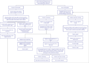
Appendix I: Troubleshooting a Problem Node
Optimized for print with Google Chrome browser.