8000 In-Pen Weighing Positions: Unloading And Assembly Instructions
Field Services - Technical Manuals
INTRODUCTION
This instruction manual describes the unloading, assembly, and start-up requirements for Vytelle In-Pen Weighing Positions.
Use the Table of Contents to guide you to specific areas. Retain this instruction for future reference.
CAREFULLY READ ALL THE MATERIAL PROVIDED BEFORE ATTEMPTING TO UNLOAD, ASSEMBLE, OR USE THE SYSTEM.
SYSTEM OVERVIEW
In-Pen Weighing Position
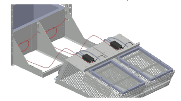
Vytelle’s In-Pen Weighing Positions measure individual animal partial body weight and growth and can be used in conjunction with the Feed Intake Nodes to provide a more accurate depiction of individual animal efficiency. The system is installed around a water trough and uses a similar style of RTU setup as the Feed Intake Nodes. The In-Pen Weighing Positions requires cattle to place their front feet on the scale to collect a partial body weight. The partial body weights are converted to an estimated full body weight as well as a hot carcass weight using a conversion algorithm. The system is also equipped with a dye spray marking system that can be used to assist in easier animal location as well as accomplishing a variety of marketing and health goals. The In-Pen Weighing Positions are commonly installed as a four-position or a six-position system, where four (or six) animals can be weighed and access the waterer simultaneously. A single DAQ panel in capable of supporting up to eight positions.
Vytelle Data Hub and Computer
All Vytelle SENSE™ systems send their collected data to a central computer that is usually kept in an office or room close to the system itself. The computer comes pre-installed with Vytelle Insight™ Software and is paired with a Data Hub, which work together to collect and display the data from the associated Vytelle SENSE system(s). The data hub collects the data wirelessly from the DAQ panels on the system(s) and stores it locally in a database file on the computer. This data is also uploaded to Vytelle’s servers in Alberta, Canada every morning at 6AM MST, where it is backed up and can be accessed and monitored by Vytelle’s Technical Service Representatives (TSR) team.
TABLE OF CONTENTS
- Safety
- Signal Words
- General Safety
- Safe Lifting
- In-Pen Weighing Position Definitons
- In-Pen Weighing Position Software
- Computer System
- Unloading the Equipment
- Moving System Around Site
- Breaking Down Pallets
- Disposing of Shipping Dunnage and Other Materials
- Assembling and Installing the In-Pen Weighing Positions
- Installing the Data Hub
- Vytelle Computer System
- Carrying Out the Internet Speed Test
- In-Pen Weighing Position Hardware
- Assembling the Vertical and Horizontal Fence Posts and Installing the Spray Assembly (If Equipped)
- Squaring and Leveling the System
- Installing the Frames and Posts
- Instaling the DAQ Post Mount, DAQ Panel, Panel Cover, and Power Supply
- Installing the Data Cables and Spray Tubing (If Equipped)
- Installing the Position Labels and Filling Spray Dye (If Equipped)
- Cable Management and Installing Vertical Post Covers and Rubber Mats
- Powering Up the System
- DAQ Dashboard & Adding DAQ Panels
- Adding Test Wands
- Testing the Spray System
- Tuning Antennas & Calibration
- Verifying Calibrations & Taring
- General Installation Troubleshooting
- No Audible Beep with Test Wand
- Calibration Baseline Does Not Return to Zero or is Not Clean
- DAQ Panel Does Not Display Correct Lights
- DAQ Panel Will Not Power On
- No GPS or Radio Lights on the DAQ Panel
- DAQ Software is Not Receiving Data from DAQ Panel(s)
- No Blinking Indicator Light at One or More Channels
- Spray System Has No Pressure or Low Pressure
- Customer Training Points
- In-Pen Weighing Position
- Vytelle Computer
- System Testing and Maintenance
- Software
- Pre-Trial Checklist
- Reports to Check Daily
- Finalizing Installation
Appendix I: Troubleshooting a Problem Node
1. SAFETY
1.1 Signal Words
Three signal words; DANGER, WARNING, and CAUTION, are used to alert you to hazardous situations. The appropriate signal word for each situation has been selected using the following guidelines.
DANGER
Indicates imminently hazardous situations that, if not avoided, with result in death or serious injury.
WARNING
Indicates a potential hazardous situation that, if not avoided, could result in death or serious injury. It may also be an alert against unsafe practiced.
CAUTION
Indicates a potentially hazardous situation that, if not avoided, may result in minor, or moderate injury. If may be used to alert against unsafe practices.
2. GENERAL SAFETY
CAUTION
Protect yourself:
When assembling, operating, and servicing any Vytelle SENSE system, wear all the protective clothing and personal safety devices that COULD be necessary for the job at hand. Do not take chances.
You may require:
- Hearing protection
- Respirator or dust mask
- Wet weather gear
- Work gloves
- Safety glasses
- CSA approved protective footwear
- Hard hat and reflective vest (depending on site requirements)
General safety considerations:
- Keep children away from equipment and machinery.
- Locate a first aid kit for use in case of emergencies.
- Be cautious around machinery and other equipment, always keep eye contact with machine operators when working and maneuvering around mobile equipment.
- Keep work site clean of obstructions, empty pallets, shipping dunnage, plastic wrap, empty boxes. These items might create tripping hazards.
- Keep work area well lit.
- Be cautious in cold or wet weather as it might make for slippery conditions.
- Be careful working with and around Vytelle SENSE system equipment as sharp metal edges can cause injury.
- Keep all tool shields in place. Never remove or alter safety equipment. Ensure all tools are in proper working order prior to system assembly.
- Identify and avoid pinch points when maneuvering Vytelle SENSE system equipment during unloading or assembly/installation.
2.1 Safe Lifting
- Do not attempt to lift by bending forward. Bend your hips and knees to squat down to your load, keep it close to your body, and straighten your legs to lift.
- Never lift a heavy object above shoulder level.
- Avoid turning or twisting your body while lifting or holding a heavy object.
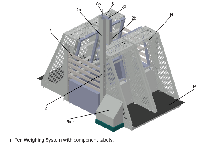
3. IN-PEN WEIGHING POSITIONS DEFINITIONS
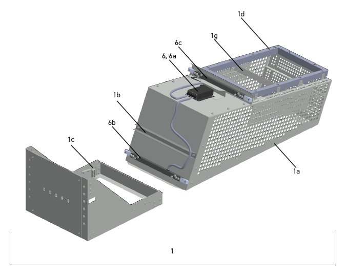
3.1 In-Pen Weighing Position Hardware
Each numbered term is represented on a set of figure drawings below the definition list for clarity.
- In-Pen Weighing Position – The assembled In-Pen Weighing Positions, including the following components:
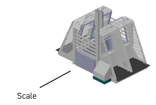
- Scale – has holes cut into side to reduce component’s weight and to reduce the claustrophobic feel for the animals. The RTU is mounted on the rear side of this component. The unit that the animals stand on to get a partial body weight. Can be tipped out of the frame for service.
- Scale floor support – metalwork component that provides space for the RTU cabling to be safely routed to ensure it is not pinched or sheared when the scale is tipped out of the frame.
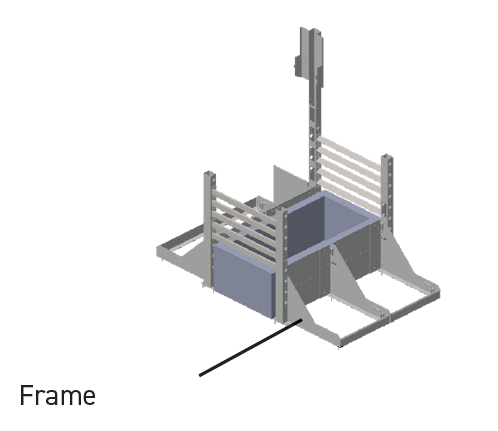
- Frame – anchors the In-Pen Weighing Position against the ground and houses the brackets that the RTUs will rest against to get weigh readings.
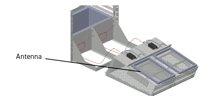
- RFID antenna – grey rectangular plastic piece bolted to the rear side of the In-Pen Weighing Position. Reads RFID tag numbers when the animals put their heads through this section to drink.
- Spray nozzle – mounted at the top of the scale, this component sprays marking paint on designated animals that have their RFID successfully read while drinking at the system.
- Rubber mat – prevents the animals from slipping when stepping onto the system.
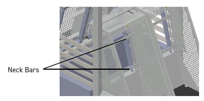
- Neck bars – prevent more than one animal from accessing the position at a time. Can be adjusted if necessary.
- Label – labels the position for clarity and consistency during service and troubleshooting.
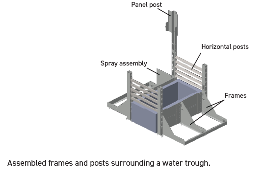
- Panel post – holds the DAQ panel, power supply, and allows for a place to rout the data cables and spray lines.
- DAQ panel mount – connects to panel post, provides location to secure DAQ panel.
- DAQ panel cover – hinged cover designed to protect data cables and power supply from animals.
- Vertical posts – posts that do not support the DAQ panel and instead provide structure surrounding the In-Pen Weighing Positions. Can be used to route data cables and spray lines.
- Vertical post cover – bolt on cover designed to protect the data cables and spray lines housed within the vertical posts from animals.
- Horizontal posts – mounted between vertical posts and/or between a vertical post and the panel post to provide further structure around the In-Pen Weighing Positions. Can be used to route data cables and spray lines. Helps to prevent animal access to water troughs from the sides of the system.
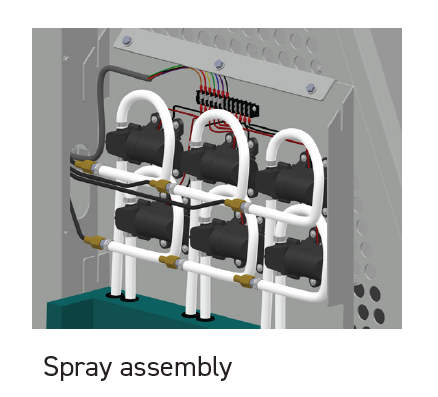
- Spray assembly (if equipped) – consists of tank to hold spray dye, a power harness, and six pumps.
- Paint tank – holds supplied Bitrex dye paint for animal marking
- Spray assembly cover – removable cover that houses the spray assembly
- Spray line – transports the dye to the individual positions. The line is routed through the posts and zip tied to the frame.
- RTU – the scale that does the weighing of the animal. Consists of an RTU box and four load cells; two load cells per bar; two bars per set. Also gathers RFID information and transmits it to the DAQ panel.
- RTU box – the device that collects the RFID data and weight information from the load cells in the load bars
- RFID antenna port – connection point for the RFID antenna
- Data cable port – connection point for the data cable
- Long bar – the bar attached to the RTU box that has longer cabling
- Short bar – the bar attached to the RTU box that has shorter cabling
- RTU box – the device that collects the RFID data and weight information from the load cells in the load bars
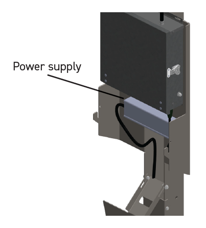
- Power supply – provides power to the system. Can be hooked to either 110vac or 240vac power.
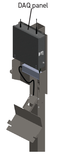
- DAQ panel – Transmits weight and RFID data to the data hub.
- GPS antenna – provides GPS radio connectivity to satellites.
- Radio antenna – provides connectivity for data transmission between DAQ panel and data hub.
- Data cable – transmits data from the RTU box to the DAQ panel. Identical to an RJ45 connector on a standard ethernet cable.
- Watertight fitting – a watertight fitting on one side of the data cable that is screwed on to the connection port at the RTU box to provide added protection from inclement weather for outdoor systems and to provide added strength at this connection point.
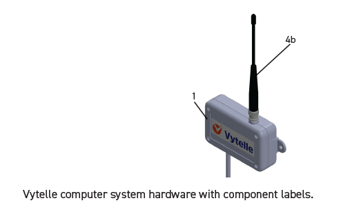
3.2 Computer System
- Vytelle computer – contains the DAQ software and records the data collected by the system.
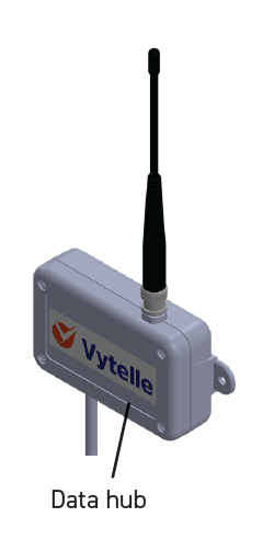
- Data hub – small black device, connected to the computer via USB cable and to a radio antenna that provides connection to the DAQ panels on the system in the field.
- DAQ software – contains the programs Vytelle support teams use to interact with the system, a way to view and interpret its collected data. Contains processes used to calibrate and set up the system for a trial.
- Radio antenna: used to connect the data hub and DAQ panels in the field. The antenna location and condition are important. Operating the system in low lying areas or terrain, under power lines or bridges, inside or through a metal framed building can severely reduce the range on the unit. Mountains can also reduce the range of the unit. There are two antenna options:
- YAGI antenna – in areas where transmission or reception is poor, some improvement may be obtained by ensuring that an antenna is mounted externally on the building that houses the Vytelle computer. Moving a few yards in another direction or moving to a higher elevation may also improve communications.
- Rubber duck antenna – simple small antenna mounted on the data hub itself inside of the office with a Vytelle computer. Generally, this antenna style is adequate for systems that are located within a clear sight line and relatively close proximity to the Vytelle computer office. This is the same antenna version used on the DAQ panels.
4. UNLOADING THE EQUIPMENT
4.1 Moving System Around Site
DANGER
Mobile equipment should never be operated without the proper training.
CAUTION
To avoid injury to bystanders from being struct by machinery, do NOT allow people to stand in the unloading area at any time.
WARNING
Use of inadequate equipment may result in equipment damage, injury and or death.
IMPORTANT:
- Palletised In-Pen Weighing Position components should be moved on or around site by the customer.
- If required, mobile equipment (tractor, skid steer, fork-lift) should be provided by the customer to move the pallets to their final location.
- Such equipment should only be operated by trained operators to ensure safety of those unloading the system.
- Use forklift or skid steer to unload each pallet from the delivery trailer.
- Move the palletised components as close to the delivery site as possible.
- If installation of the system is not going to occur immediately, ensure that the system components are stored out of the elements where possible until such a time that they are to be installed.
- Ensure that pallets are unloaded onto a level surface.
- Check In-Pen Weighing Position components for any external shipping damage.
4.2 Breaking Down Pallets
- Remove straps holding units to pallets.
- Be aware that items may have shifted during shipping resulting in imbalance or slipping once straps are removed.
- Remove any loose items packaged with In-Pen Weighing Positions and set these aside.
- Tilt scales out of frames.
- If installation is to occur immediately, move the frames into their approximate positions.
- Inspect the unpacked shipment for missing components by comparing with the shipping manifest.
- Collect all shipping materials (straps, bolts, plastic, etc.).
4.3 Disposing of Shipping Dunnage and Other Materials
After pallets have been unpacked, collect all shipping waste to a central location. Contact the customer or site manager to discuss their preferred method of disposal for these items and dispose of dunnage accordingly.
IMPORTANT: Ensure ALL Vytelle scrap metal is collected from the customer site prior to technician departure.
5. ASSEMBLING AND INSTALLING THE IN-PEN WEIGHING POSITIONS
5.1 Installing the Data Hub
- Obtain the supplied data hub from the shipped Vytelle SENSE system equipment and screw on the supplied radio antenna to the top of the data hub.
- Remove the protective tape on one of the adhesive sides of the supplied Velcro tape and apply it to the back of the data hub.
- Locate the designated Vytelle computer at the site (generally in an office or building near the Vytelle SENSE system but may have been sent with the system shipment) and install the data hub on the side of the computer tower or the wall above the computer.
- For best placement, install the data hub near the Vytelle computer whenever possible.
- Connect the USB cable to the relevant port on the data hub and connect the other end of the cable to a USB 3.0 port on the Vytelle computer, a power light should be displayed once this cable is plugged in.
- USB 3.0 ports are identified as blue ports versus the standard black or white ports that represent USB 2.0.
5.2 Vytelle Computer System
IMPORTANT: The customer is responsible for the installation of the Vytelle computer and for setting up the computer’s log-in information. When you arrive on site, be sure to verify that the computer installation has occurred or will be occurring, as soon as possible. Log-in information must be communicated to the Technical Support team (support@vytelle.com) and the computer must be connected to the internet to allow mandatory installation updates to be completed by the IT Services team. It is important that as soon as the computer has been connected to the internet you contact your Field Service Coordinator or Vytelle IT (it@vytelle.com) with your site information to make sure that the computer and the software are configured correctly.
The Technical Support and IT Services teams that remotely monitor and maintain the system access the customer’s computer through a program called LogMeIn, which requires an internet connection to be fully functional.
5.3 Carrying Out the Internet Speed Test
- Open a web browser on the Vytelle computer and navigate to the Google home page.
- Type ‘speed test’ into the search bar and click the blue ‘Run Speed Test’ button on the first search result.
- Allow the test to run and record the resulting download and upload speeds on the installation commissioning checklist.
5.4 In-Pen Weighing Position Hardware
IMPORTANT: Always refer to the site layout drawings prior to beginning installation of any Vytelle SENSE system equipment. Ensure all installations match the provided site layout. Contact your Vytelle Field Service Coordinator PRIOR to installing any equipment if there are discrepancies between the intended layout and what is possible at the site.
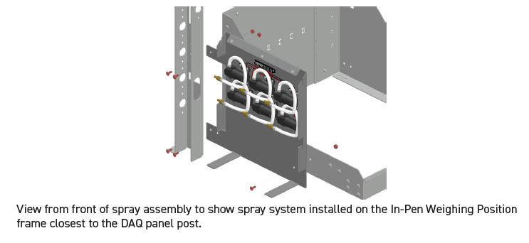
5.4.1 Assembling the Vertical and Horizontal Fence Posts and Installing the Spray Assembly (If Equipped)
- Move the In-Pen Weighing Position scales and frames into position around the water trough. Position them squarely in front of the water basin of the trough.
- If the site drawing calls for two or three positions to be located beside each other, space the frames 3/4” (20mm) apart from each other.
- Tip the scales out from the frames (with your foot placed on the frame, pull from the upper lip of the position near the spray nozzle to tip the scale out of the frame).
- Lay out your vertical fence posts around the tough in the locations depicted in the drawing. The long post with one tab at its base is the panel post. The shorter posts with two tabs at their bases will be installed at the other corners of the system.
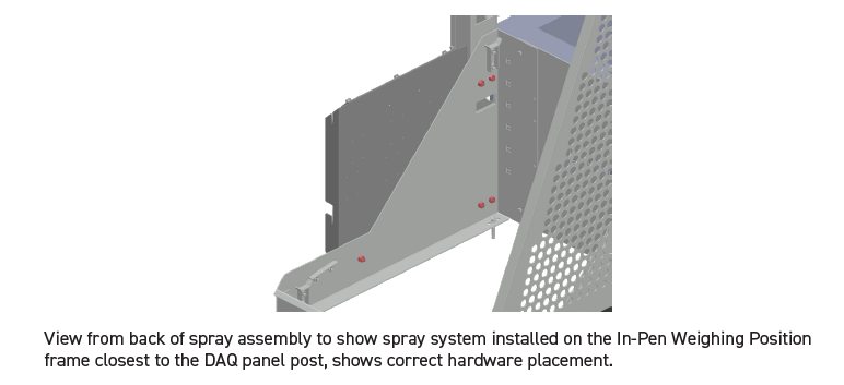
IMPORTANT: if the In-Pen Weighing Positions are equipped with a spray system, you will want to install the spray assembly between the taller panel post and the In-Pen Weighing Position frame that will be attached to that post. Consult your site layout drawing to be sure the location of your panel post and spray assembly are correct. Use a large screwdriver or hole punch to align the holes in the two tabs with the holes in the frame and panel post. Use the 3D printed handles in the customer toolkit to remove the spray assembly cover and secure the third bolt behind the grey dye tank. Install ALL your hardware finger tight before tightening with power tools.
- Using four 3/8” (10mm) carriage bolts and lock nuts per post, install each fence post to the outside corners of the In-Pen Weighing Position frames. The bolts should come in from the panel post and the nut secured from the inside of the In-Pen Weighing Position frame. Repeat this at all vertical fence posts.
- Using the 3/8” (10mm) carriage bolts, bolt five triangular horizontal fence posts between two vertical posts so that all five horizontal posts are oriented the same way (pointed faces of the triangular bars facing in toward the water trough). Install all your hardware loosely before tightening to aid in assembly.
- You may need to omit some bars depending on the water trough design. Always install enough fencing to prevent animals from accessing the water trough from the sides.
- Bolt five additional horizontal fence posts between the remaining vertical post and the DAQ panel post, again ensuring that each bar is oriented the same way. Be sure to install the taller, single tabbed DAQ panel post on the correct side (either left side or right side) as per the site layout.
5.4.2 Squaring and Leveling the System
Once both the vertical and horizontal fence posts have been installed you can now square and level the system to the trough and concrete pad prior to securing it. This must be done with the scales tipped into the frames in their operational position. This way you can make sure the scales do not rub on the trough or any nearby pen fencing.
- Shift the frames back and forth until the parts of the frames that are closest to the trough are equally distanced and that the area where the animals drink from is as centered as possible to the water basin of the trough. Verify all measurements with a tape measure.
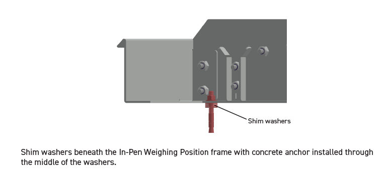
- Using a spirit level, check all the frames for level on all 4 sides. The system must be level when it is secured to the concrete. If the frames require leveling use the supplied shim washers to level each position, slide the supplied shim washers under the frame’s four corners to level it. Ensure that the shims are centered around the anchoring hole as you go. Make sure to maintain the placement around the trough and the 3/4” (20mm) gap in between the adjoining frames.
- Mark the concrete pad around the edges of the system to help you keep the frames square for the next step.
5.4.3 Installing the Frames and Posts
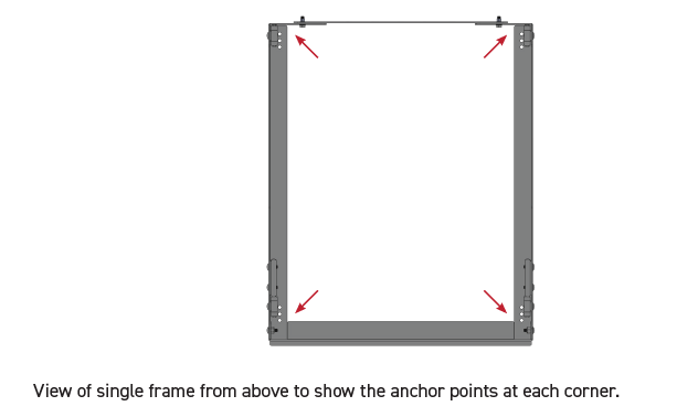
- Use a hammer drill to drill 3/8” holes at each of the four corners of the frame and then hammer in a concrete wedge anchor at each corner. If you have had to level the frames with shim washers, make sure to drill through the center hole of the shim washers to lock them into position. You will use four cement anchors for each frame.
- Verify that each frame remained level during the anchoring process. If all frames are level, install four additional cement anchors per vertical post and verify that the posts are level horizontally and vertically before moving on. If the tabs at the base of the posts are not level with the concrete, use shim washers to fill the gap before drilling and installing anchors.
- If any component is not level upon re-checking, release the cement anchors on that component and modify the number of shims supporting the component such that the component is level. Then, re-install the anchor nut and verify the component remains level. In the event you cannot level the component with shims, you may have to re-anchor the component by drilling a new pilot hole and re-anchoring the component. Before attempting to re-anchor the component, ensure it is level and square. If you must move a frame or a vertical post, be sure to re-measure to ensure all components are distanced appropriately before moving on.
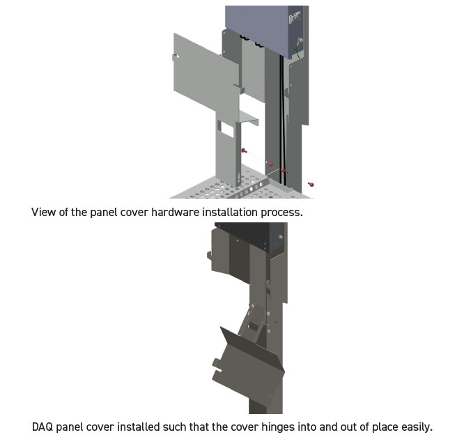
5.4.4 Installing the DAQ Post Mount, DAQ Panel, Panel Cover, and Power Supply
- Raise the DAQ post mount into position on the tallest post on the system and secure it into position with four self-tapping, 1/4” thread forming bolts supplied in the In-Pen Weighing Position hardware bag. The panel post opening must face towards the installed frames. Make sure the panel is in the same location and orientation as in the site drawing.
- Obtain one DAQ panel and record the address listed inside of the door and write down the pen location (reference the site layout drawing for panel and pen locations, i.e., Panel #1 Address #: 4157D9E2; Panel #2 Address #: 4157D9A7; etc.).
- Screw in the GPS antenna and the radio antenna to the top side of the DAQ panel.
- Maneuver the cut-outs on the back of the DAQ panel onto the hooks on the DAQ post mount such that the DAQ panel is fully supported by the DAQ post mount and the panel post.
- Use two 3/16 (8mm) head self-tapping screws to secure the bottom of the DAQ panel onto the panel post. Thread one of the screws through the ring terminal on the green ground wire before installing it to ground the panel.
- Hinge the DAQ panel post cover into position and instal with the supplied two ¼” x ¾” (6mm x 20mm) hex-head bolts, four ¼” (6mm) washers, and two ¼” (6mm) lock nuts. Tighten so that the panel post cover can be slid in and out of position easily.
- With the cover in the open position, mount the power supply underneath the DAQ panel using self-tapping screws and the supplied holes in the panel post. The DAQ panel plug end should be facing to the right when looking at the power supply mounted on the post.
- Ensure the panel cover closes properly before moving on. If the cover is unable to close properly, move the power supply accordingly. If the system is equipped with spray functionality:
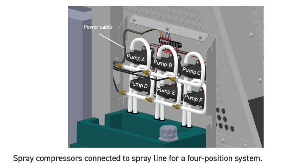
- Route the grey power cable from the spray assembly up to the DAQ panel and plug it into the panel.
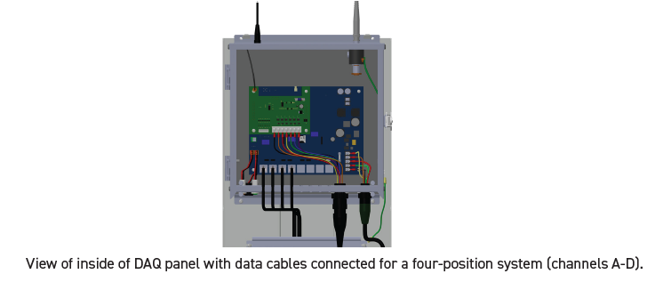
5.4.5 Installing the Data Cables and Spray Tubing (If Equipped)
Using the site layout drawing, find the cable lengths required for the system, collect the specified data cable lengths, and arrange them from shortest to longest. The In-Pen Weighing Positions are labelled alphabetically. The position that the DAQ panel is mounted nearest is always Position A. While facing Position A, the position on the left is Position B. Continuing counterclockwise down and around the water trough are Positions C, D, E, F, and so on.
- Pull the scales up to the frames so that they are either resting on the lip of the frame or, so they are no more than 1’ away from the frame.
- Connect the cables with the lengths that match the ones in the site layout drawing to the RTUs on the scales that are tipped out of the frames. Connect the end with the watertight seal to the RTU.
- Once all cables are connected to their respective RTUs, label them with a marker according to their position. Use a cable labeler or mark the side of the RJ45 connector.
- Ensure the watertight twist-seal is secured on each RTU box before moving on
- Run each cable through the rectangular cut-outs on the frame toward and into the cut-out on the DAQ panel post.
- If you have positions on the opposite side of the water trough, run the cables through the cut-outs toward the side of the system with the panel post, through the cut-out on the bottom of the short vertical fence post (same side of the system as the panel post), then fish the data cables through the triangular horizonal fence post.
- Install all data cables up into the DAQ panel into their respective channels (Position A will be plugged into the A port, Position B will be plugged into the B port, etc.).
- Pull any excess slack back toward each individual position, as it will be secured along the back plate of the frame at a later step.
If the system is equipped with spray functionality:
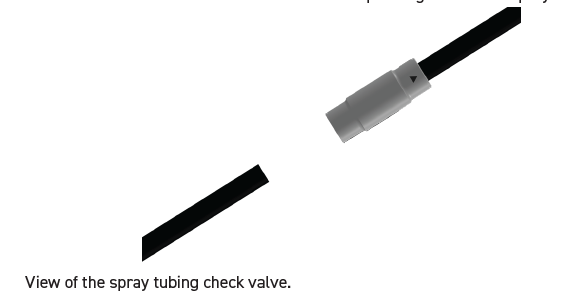
Starting at Position A, press the spray tubing into the check valve installed on the scale, make sure the check valve is installed so that the arrow is pointing toward the spray line installed on the scale.
Run the tube alongside the data cable through the cut-out the data cables are in and then
90- degrees into the spray assembly. Locate the pump labelled A, cut the tube to the appropriate length, and then press the tube into the fitting.
Secure the tube to the data cable using cable ties. Repeat this process with all other positions making sure to have the tubing follow the data cables.
Fish the tubes on the opposite side of the trough through the triangular horizontal fence posts the same as you did the data cables. You can use a different fence post if there is not enough room.
Once all the tubes have been tied to the data cables, secure the loose cables to the cable tie cut-outs on the frames. Have the cable for each position secured in the center of each frame. All excess cable slack should be gathered neatly and secured with cable ties to the frame such that it will not contact the scale as it is moved in and out of position.
IMPORTANT: If there is any welding that needs to take place to complete pen fencing or the installation and or routing of power or water take care not to burn the cables or tubes inside the fence posts.
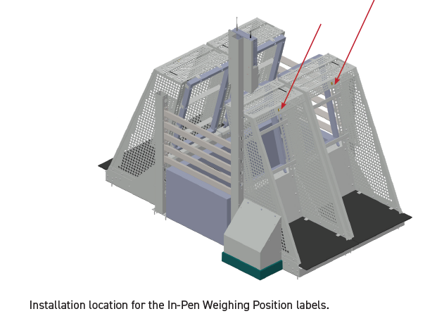
5.4.6 Installing the Position Labels and Filling Spray Dye (If Equipped)
- Tip the scales back into position being careful not to pinch a data cable or spray tube.
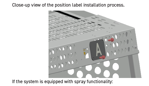
- Locate the position labels and apply them following the site layout. The position closest to the DAQ panel will be Position A. Labels should be applied over the cut out that gives a view of the spray nozzle such that the nozzle is not visible from the front of the unit.
- Use a 1/4” (6mm) thread forming bolts to secure two of the four corners of each position label to the scale.
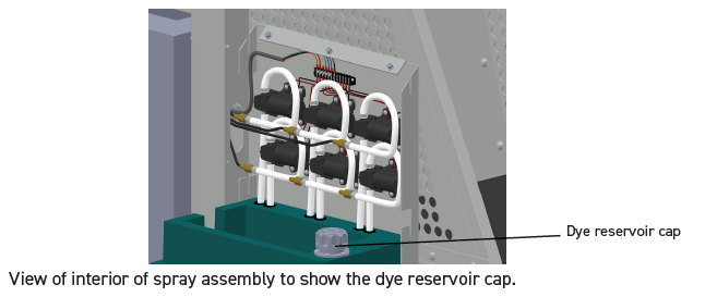
- Remove the dye reservoir cap by turning it counter clockwise.
- Open the supplied dye bucket and carefully empty it into the dye reservoir, one bucket per reservoir.
- Replace the dye reservoir cap and secure it by turning it clockwise until it is finger tight.
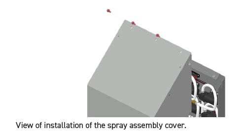
- Reinstall the spray assembly cover by sliding it into place and then fastening it with three 1/2” (13mm) drive bolts.
IMPORTANT: The customer is responsible for installing electrical at this point in the installation, communicate this requirement with the site manager or your site contact before moving on. Be sure to establish the correct position for the power outlet on the system. The receptacle is to be located inside the DAQ panel post and the routing of conduit cannot interfere with the scales or block the panel post covers. Power can be run in any of the following ways:
- Down from the top into the post.
- Along the fencing, into or along a horizontal fence post, and up into the post.
- Along the concrete pad and up into the DAQ panel post (modification of the panel post cover may be required).
5.4.7 Cable Management and Installing Vertical Post Covers and Rubber Mats
- With all cables and spray lines fully routed, begin securing all cables and lines with the supplied zip ties using designated cut outs on the In-Pen Weighing Position metal work (i.e., secure to frames and within the DAQ panel post).
- he data cable and the spray line of each position should be zipped together wherever possible.
- Gather excess cable and line slack at the back of each position and secure it neatly with a zip tie.
Data cables and spray lines secured to In-Pen Weighing Position frames with zip ties. Note that any slack is secured neatly to the frame such that it is in no danger of being pinched or caught when the position is moved in and out of place for servicing.
- Once all cables and lines are secure, install the vertical post covers on each of the three vertical posts (not the DAQ panel post) using 3/8 thread forming bolts on each side of the cover.
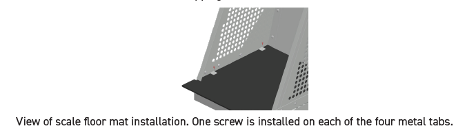
- Place one supplied rubber mat on the floor of each position. The mat should be oriented such that the end with the two flared edges is facing the front of the position (i.e., where animals will enter the position).
- Slide the mat into place underneath the mat anchoring cut out tabs on the In-Pen Weighing Position scale metalwork and install a self-tapping screw at each cut out to anchor the mat.
IMPORTANT: Ensure that all cables and spray lines are secured such that there is no danger of them being pinched or sheared when the scale is tilted in and out of the frame. Be sure to leave sufficient slack in both the spray lines and data cables to allow the position to be tipped in and out of position without putting any tension on the cables/lines.
5.4.8 Powering Up the System
- Once electrical is installed, plug the power supply into the electrical outlet and then plug the power supply into the DAQ panel. You should see lights appear on the DAQ panel to indicate that it is running.
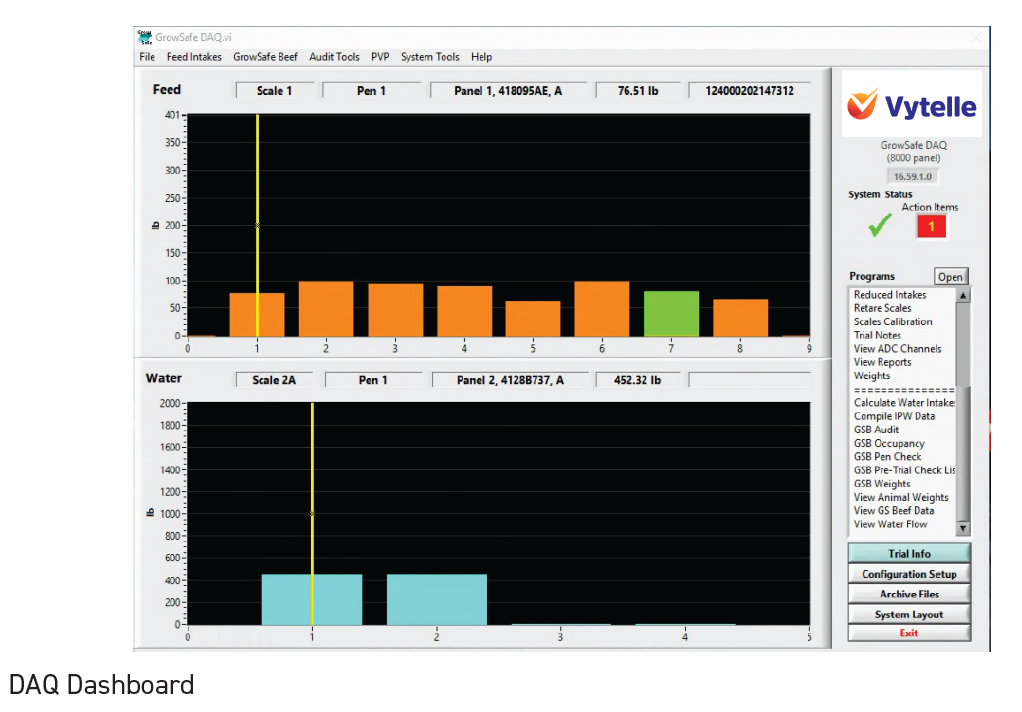
5.5 DAQ Dashboard & Adding DAQ Panels
- At this point you should have received word of the computer’s correct configuration. If not, contact your Field Service Coordinator to make sure that is has been completed.
- The Vytelle computer is set up to auto-login and launch the DAQ software and Watchdog. If these two programs do not launch automatically contact Vytelle IT (it@vytelle.com)
Watchdog and DAQ Dashboard software.
IMPORTANT: If you do not have a username and password with the credentials required to make system changes, you are unsure of your user credentials, or you are having any technical issues with the following steps, please contact your Field Service Coordinator to have the following tasks completed.
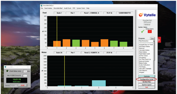
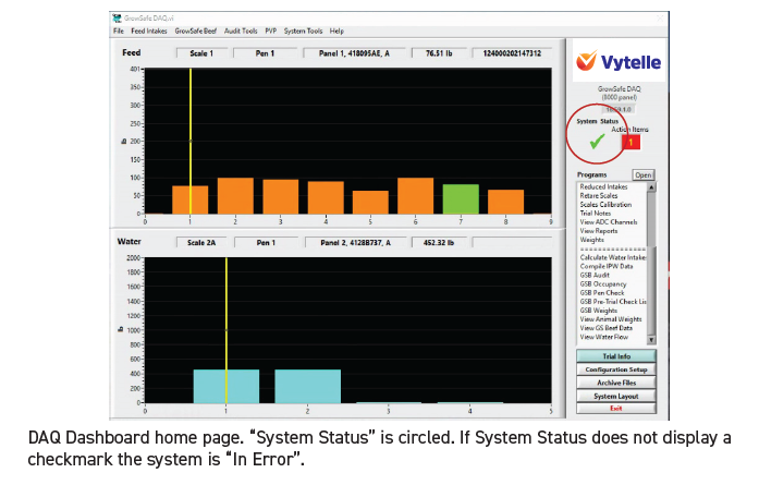
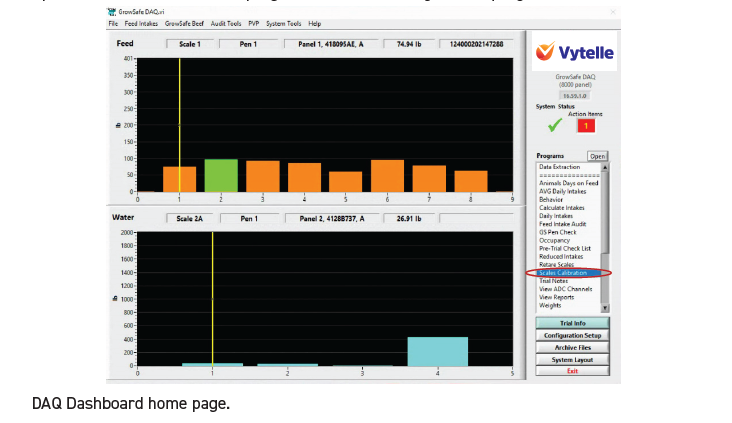
Click the “Configuration Setup” icon in the bottom right of the DAQ software Dashboard.
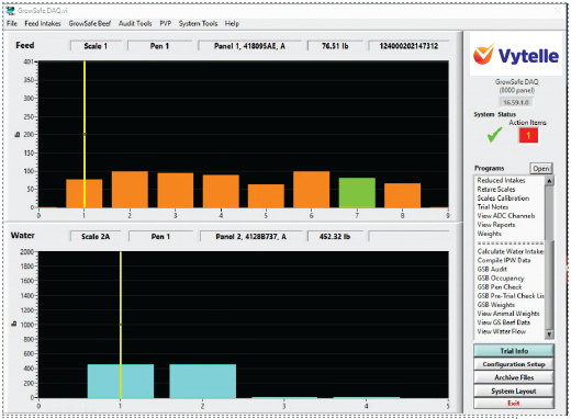
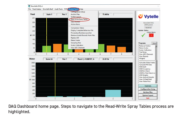
DAQ Dashboard home page.
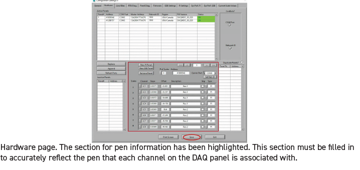
Click the “Hardware” tab located in the top left of the Configuration window.
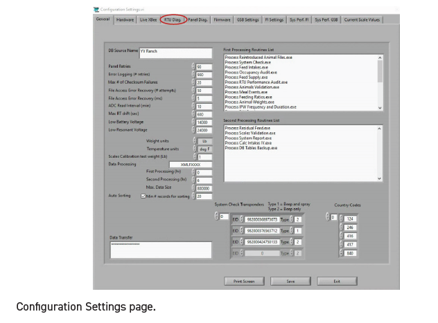
Configuration Settings page:
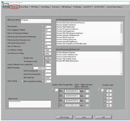
With the panel(s) online and connected to the data hub the address number(s) should show up in the “Active Panels” list. Note the positioning of each panel on the side layout drawing and its address as this is important to have them configured correctly. (i.e., if the first panel has positions 1- 4 in pen 1 and 5-8 in pen 2, the second panel has positions 9-12 in pen 3 and 13-16 in pen 4, the software must reflect that to collect accurate data – see below for example).
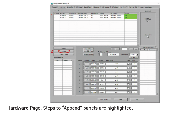
If the “Inactive Panels” list is empty, you can select the first panel on your Active Panel list and click the “Append” icon in the center left of the Hardware page. Do this with all the panels listed in the site layout drawing.
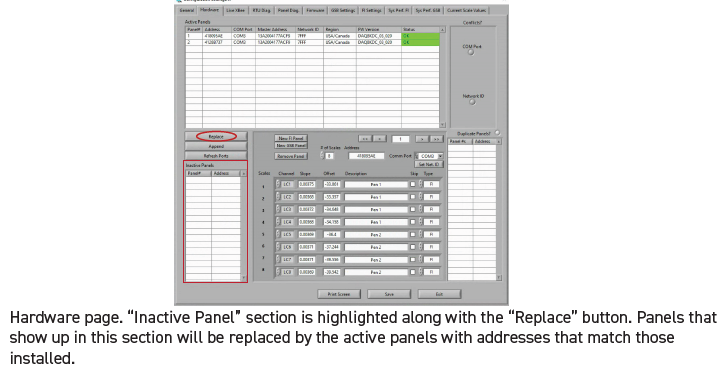
If the “Inactive Panels” list is already populated with the correct number of panels that you installed, you can select the first panel out of the Inactive Panels list and the first panel in the Active Panels list that matches your earlier recorded list and click the “Replace” icon in the center left of the Hardware page.
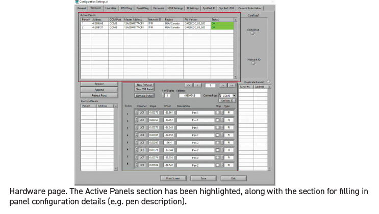
After you have successfully added the panels you should see the panel numbers displayed that match the list of installed panels. You can then go through each panel in the “Active Panel” list and type in the correct pen information for each scale. Example: Panel #1 A-C are in pen 1 and D-F are in pen 2).
Once all the scales on all the panels have been labelled correctly make sure to save your changes with the icon at the bottom of the window. You will be prompted to enter your username and password each time you save changes to the system. It is preferred that you also leave a brief note detailing the changes you have made at this time.
Once your changes have been saved, exit out of the Configuration window, and restart the software. You may need to use the task manager to close out the software. Once the DAQ software has restarted, the red bars on the dashboard should turn white and there should be a green checkmark displayed in the top left corner when communication had been established.
If the bars are still red, then check the following:
- There may be a power issue in the field. Check the green power and orange DAQ status lights of all your panels in the field. Open their covers and make sure that all the green channel status lights are flashing as well as the Radio and GPS lights.
- If power is okay, open the “Configuration Setup” window and check the status of the panels in the active panels list. They should all read “OKAY” in green. If they are listed in the “Inactive Panels” list then double check the antenna connection, USB connection, and the power lights on the data hub. If the bars are still red, contact your Field Service Coordinator for assistance.
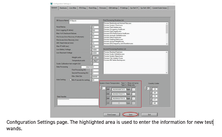
5.5.1 Adding Test Wands
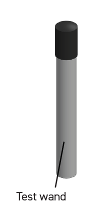
The Vytelle SENSE system support two different types of test wands: a spray wand and a beep wand. The spray wand is used to test the functionality of the spray system on the In-Pen Weighing Position and will engage the spray mechanisms (i.e., the system will spray paint) when the wand is used. The beep wand will force the system to emit an audible beep to verify that the system is reading an RFID. Both wand types can be used to calibrate the system, though the beep wand is recommended for routine calibrations to avoid unnecessary spraying of paint.
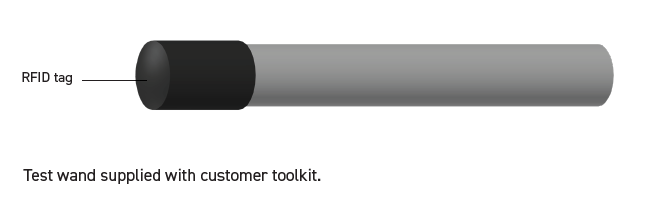
- Locate the customer toolkit that was supplied with the shipment and obtain the test wand(s).

- Open the “Configuration Setup” window and enter the test wand number found on the wand label and test wand type (spray wands are Type 1, beep wands are Type 2) in the lower right hand of the window. Save your changes with your user credentials.
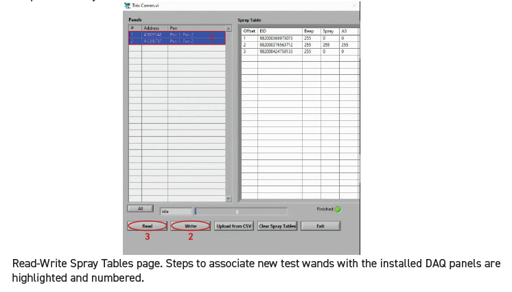
- Close the “Configuration Settings” window and open the “Read Write Spray Tables” program located in the “System Tools” drop down at the top of the DAQ dashboard.
- Select all your panels and click the “Write” icon. Wait for it to finish and the hit “Read” to make sure the panels have your test wand numbers stored on them.
5.5.2 Testing the Spray System
- Using the spray wand, test each position in alphabetical order to ensure that the spray lines are connected in the correct order and that each position has sufficient spray pressure.
- If any spray lines are out of order upon testing, remove the spray system cover and move the affected spray lines to the correct compressor and re-test to ensure correct line placement.
- If any position is experiencing low spray pressure, check the associated spray line for leaks. If the line is leaking at a connection point (near the RTU or in the spray assembly), verify that the line was not cut at an angle (if it was cut at an angle, re-cut it such that it is cut straight across) and reconnect the line and re-test. If the line is leaking elsewhere, replace the line and re-test.
5.5.3 Tuning Antennas & Calibration
Tuning is done to automatically set the resonate voltage of the antenna to optimise RFID tag reads. Tuning is performed after the instillation of a new RTU.
Calibration is used to ensure that the scales in the RTU’s are functioning correctly. Calibrations only need to be performed after the installation of a new RTU or on the entire system prior to the customer starting a trial.
Taring is performed after calibration to set the zero-point displayed on the DAQ software.
As part of an installation, all scales will be calibrated and tared.
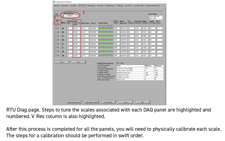
- Open the “Configuration Setup” window and select the “RTU Diag” tab at the top center of the window.
- Select your panel in the top left of the window and then click “Tune All” the process will work through all the scales individually. You can follow the process along by watching the number in the V Res column. When the scale antenna is tuning it will display “65553” when the tuning has been completed successfully the number displayed should be between 1100-1300. If the number is lower than 1000, inspect the pigtail and antenna connections on the position in question.
- Retrieve the two 50 lb calibration weights that were shipped with the equipment.
- Starting at the first scale, place the certified weights on to the floor of the scale and wait for approximately two seconds for the system to level.
- WITHOUT TOUCHING THE SCALE, hold the test wand in front of you such that it is positioned in the center of the grey antenna with the black tip toward the water trough and allow the system to beep fifteen times.
- Repeat this process on all scales in the system, calibrate all positions on the system in alphabetical order.
IMPORTANT: If you do not have the user credentials to make system changes or you are having technical difficulties, please contact your Field Service Coordinator to have the following tasks completed. Once the calibrations have been completed note the time and weight on the “Trial Notes” program located on the DAQ Dashboard and notify your Field Service Coordinator to have the calibrations checked.
5.5.4 Verifying Calibrations & Taring
You will need to restart the DAQ software to get the system to pull the most recent data from the panels. If you have done your calibration within ten minutes of trying to check them, you will likely need to perform this task. Then you need to open file explorer located in the task bar and copy the “Configuration” folder. Paste a copy of it inside the “Saved Configuration” folder. Once your configuration has been successfully pasted, you can close the file explorer.
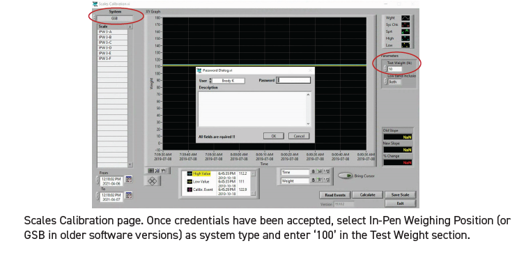
Open the “Scales Calibration” program located in the right-hand program list.
The program will prompt you for your user credentials and a description of what you are calibrating. Once you have entered this you can begin checking calibrations.
- Select In-Pen Weighing Position (or GSB in older software versions) as the “System Type” and enter 100 lb in the weight setting.
- Select the first scale off the list on the left-hand side of the window and work down from there.
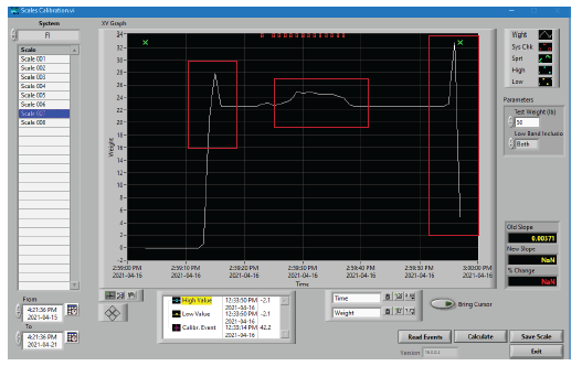
- Once you select a scale you should be see the calibration you performed displayed on the graph. The graph should look clean with a clear rise in weight when the calibration was happening, a good leveling off during the calibrations, and a nice even baseline after the calibration is completed. See below for examples of acceptable and unacceptable calibrations.
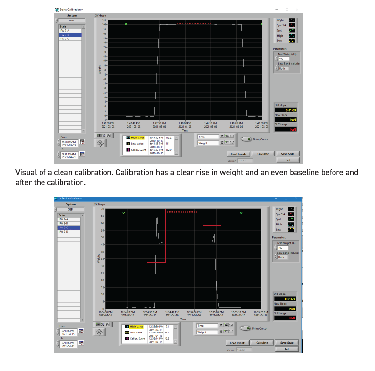
Visual of an acceptable calibration. The spike visible to the left and right suggest that the scale was briefly leaned on while placing the test weights onto the scale. which ideally should be avoided, but in this case the calibration was not compromised since the scale was given time to level out before inserting the test wand to calibrate.
Visual of an unacceptable calibration that will have to be re-done. The left baseline is missing from the calibration, suggesting that the test wand was inserted too late after the test weights were placed on the scale.
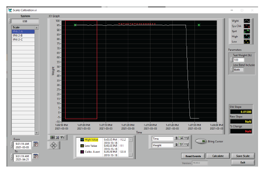
Visual of an unacceptable calibration that will have to be re-done. The right baseline is missing which suggests that the test weights were removed too late after the test wand. The spikes at each end suggest that the scale was contacted while the test weights were placed on and removed from the scale, which is okay, but the bump in the middle of the calibration suggests that the scale may have been contacted while the test wand was beeping the system.
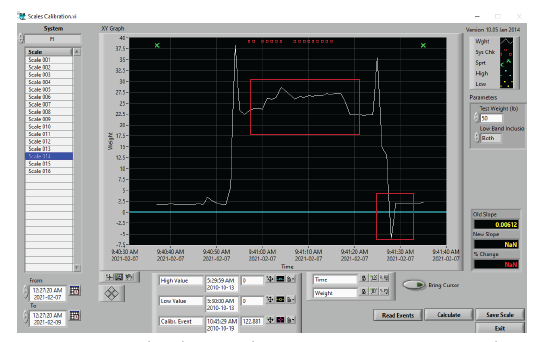
Visual of an unacceptable calibration that will have to be re-done. The calibration itself was not clean, suggesting contact or shifting of the scale during calibration, but the more concerning issue is that the baselines do not match up on the left and right sides. Recalibrate and if this does not fix the issue, troubleshoot with Technical Support.
Click the “Bring Cursor” icon and make sure the purple line is located between the calibration events, click “Calculate” and then “Save”. Repeat this on all calibrations performed.
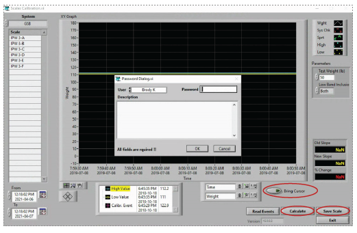
Scales Calibration page. Relevant buttons for navigating scale calibrations are highlighted.
IMPORTANT: Only click “Save” one time. Multiple clicks of the “Save” button with exponentially change the slope and the calibration will have to be re-done.
6. GENERAL INSTALLATION TROUBLESHOOTING
6.1 No Audible Beep with Test Wand
First, confirm that the test wand was added to the panel correctly. At the Vytelle computer, open the “Configuration Setup” window and confirm the test wand number listed in the system matches the number of the test wand you intend to use. Save any of your changes with your user credentials.
If the test wand number was entered correctly, sometimes re-writing and re-reading spray tables will fix the error. Accomplish this by following these steps:
- Close the “Configuration Setup” window and open the “Read Write Spray Tables” program located in the “System Tools” drop down at the top of the DAQ dashboard.
- Select all your panels and click the “Write” icon. Wait for it to finish and then hit “Read” to make sure the panels have your test wand numbers stored on them.
- Test the test wands on the system.
If all positions on a particular DAQ panel do not beep, but the status light at the bottom of the DAQ is flashing to indicate the test wand is being read (when the wand is tested) AND the test wand is being registered on the Vytelle computer; the component of the DAQ panel that emits the sound, the beeper, likely needs to be unplugged and plugged back in or replaced entirely.
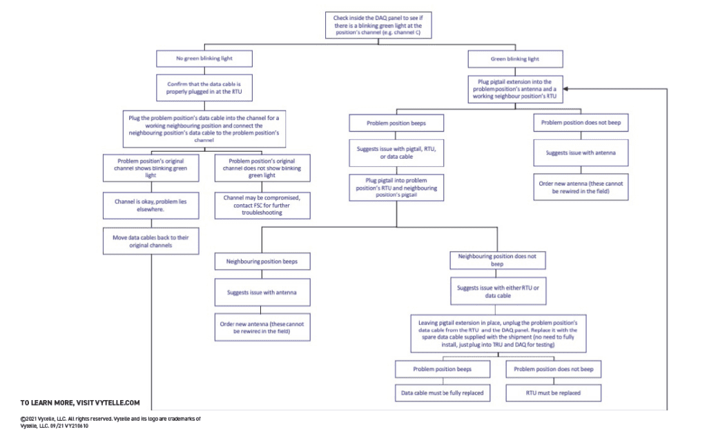
If the problem is with one or more positions individually, refer to the troubleshooting flow chart in Appendix I.
6.2 Calibration Baseline Does Not Return to Zero or is Not Clean
This is usually the result of rubbing between the scale and the frame at the affected positions.
Check to confirm that the scale is not hung up on the frame somewhere and that the scale is sitting correctly on the load bar brackets (inside of the frame). A few common questions to work through:
- Is the scale positioned correctly on the RTU brackets? When the scale is in its upright position, you should be able to place your hand on the top lip of the scale (where the spray nozzle is located) and apply pressure to tip it back toward the water trough. As you do this, the scale floor will move up out of the frame, since the back set of brackets act like a hinge for the scale during this motion. If you cannot tilt the scale back toward the trough and/or the scale floor does not move freely out of the frame, tilt the whole scale out of the frame, reposition it so that the bottom load bar will contact its associated brackets inside of the frame, and then tilt it back into position. When it in the correct position, the scale floor should sit flush with the top of the frame when viewing the position from the front. When viewing the position from the back (or side if possible) there should not be a vertical gap between the lip that houses the upper load bar and the frame.
- Am I accidentally leaning on the scale or contacting it as I am calibrating? If you must lean or step on the floor of the scale to place the calibration weights on the scale floor that is okay, but if this is the case, you must wait two seconds to start beeping the system after you have placed the weights, and you should wait two seconds to remove the weight after you are finished beeping the system. This will prevent you from compromising the calibration baseline. You should not be contacting the scale or the frame at any point during the insertion of the beep wand or the beeping of the system.
- Does the calibration look cleaner if I swap the scale at the affected position with a different scale? Sometimes minor differences in the scale and/or frames can contribute to rubbing and this might be an easy fix.
- Are the load bar brackets installed correctly? Confirm that the brackets and their associated carriage bolts are installed correctly and fully tightened. The brackets should not be able to be tipped away from the frame or moved up and down.
- Are the RTU load bars installed at an angle by mistake? Loosen the bolts that mount the RTU load bars to the scale, and re-install the bolts ensuring that the load bars do not twist or lean as the bolts are tightened.
- Is anything touching the scale that should not be? Is the scale contacting any of the pen fencing or the water trough when it is in its upright position in the frame? Is there any debris under the scale that could be contacting it? Do a thorough check and cleaning. Ensure all cables are properly secured to the scale and the frame and remove any potential obstacles below or around the trough that might interfere with its ability to sit freely on the load bars. If pen fencing or the water trough are contacting the scale you may have to move the positions and re-anchor them.
- Does the RTU need to be replaced? Have a discussion with the site’s Vytelle Technical Support Representative and ask them whether the calibration might indicate that the RTU is malfunctioning. If this is the case, the RTU may need to be replaced.
6.3 DAQ Panel Does Not Display Correct Lights
6.3.1 DAQ Panel Will Not Power On
Confirm the panel has adequate power and is plugged in and have a qualified person verify the power to the DAQ panel is functional.
If the power to the power supply has been verified and the panel does not power up, unplug power from the panel, remove and inspect the 20 mm 6 AMP glass tube fuse from the DAQ panel. If the fuse has been compromised, unplug all the data cables from the DAQ panel (being sure they are labelled to be plugged into the correct channel after troubleshooting is complete).
With the new fuse installed and the power supply plugged in, start plugging in the cables one at a time. Make sure to wait until their respective indicator light blinks green before plugging in the next cable. If the fuse blows again while you are plugging in the data cables, stop and fully inspect the specific cable that caused the fuse to blow for damage. Likely the cable has been damaged somewhere along its length and is creating a short, meaning the cable will have to be replaced with the supplied spare.
Repeat the above process until all data cables are plugged back into their respective channels and the panel remains powered on. Take care not to mix up the cables. If the DAQ panel fuse still blows after the data cable is replaced on the affected position, the RTU may need to be replaced.
6.3.2 No GPS or Radio Lights on the DAQ Panel
Whenever the DAQ panel’s orange status light is not flashing or the GPS and radio lights inside the panel are not illuminated, the DAQ panel is not transmitting data.
Confirm that the GSP and radio antenna have not been damaged on top of the DAQ panel. Disconnect both antennas and then reconnect them. Cycle the DAQ panel power (i.e., unplug the power chord, wait for 30 seconds, and then plug the power chord back into the DAQ panel) and wait for the GPS, radio, and panel status lights to turn on (orange status light flashes every 0.5 seconds). It may take up to 5 minutes to establish a GPS connection.
If the lights do not come on, there is a chance that the building’s roof that houses the system is made of a material that is blocking the communication and a stronger antenna may be required
(contact your Field Service Coordinator for further instruction). Otherwise, the panel should be replaced.
6.3.3 DAQ Software is Not Receiving Data From DAQ Panel(s)
Confirm that the DAQ panels are transmitting (i.e., the DAQ panel’s orange status light is blinking on a 0.5 second interval). Verify that the data hub is connected to the Vytelle computer and that it displays a green power light at the bottom. If no power light is visible, the data hub may need to be plugged into a different USB port. Ensure the data hub’s antenna is secured tightly.
If you have long-range Yagi antennas installed, ensure that they are correctly aimed at each other. There is a possibility that the line of sight from the DAQ panel to the data hub has been obstructed and the Yagi antenna may need to be mounted at a higher elevation.
If you are still having communication issues, contact your Field Service Coordinator for further troubleshooting.
6.3.4 No Blinking Indicator Light at One or More Channels
Troubleshoot following the flow chart in Appendix I.
6.3.5 Spray System Has No Pressure or Low Pressure
Symptoms of pressure loss in the spray system typically include a ‘dribbling’ spray when the system is prompted to spray with a test wand.
Check the connection points for the installed spray hose (at the compressor and on the back of the In-Pen Weighing Position scale) for signs of a leak. If you observe a leak, disconnect the spray hose, and trim the end of it to ensure it is straight. Reconnect and re-test with the spray wand. If pressure is not restored, check the length of the hose for leaks and replace if necessary. Otherwise, check to see that the spray nozzle is not obstructed and confirm that the compressors are engaging when the spray wand is used.
When the spray system is first tested with the spray wand, it will take several sprays to remove air from the line and fill it with paint. Ensure you have allowed an adequate number of sprays for the system to pressurize.
If the problem cannot be resolved. Contact your Field Service Coordinator for further troubleshooting.
7. CUSTOMER TRAINING POINTS
7.1 In-Pen Weighing System
System components starting roughly in order of troubleshooting.
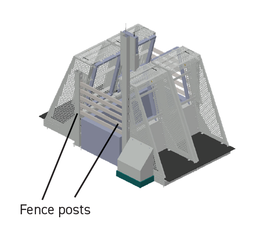
Vertical and horizontal fence posts:
- Restricts access to the sides of the trough, holds data cable and spray lines.
Frame:
- Leveled and anchored to concrete.
- Supports load cells on position to allow for accurate weights.
- Has a solid back to prevent water and soil from building up underneath the position and negatively affecting the weight reading.
Scale:
- Is the unit that the animal steps on so we can collect the front-end animal weight.
- Holds the RTU, antenna, and spray nozzle.
- Rubber mat installed for additional traction.
Neck Bars:
- Only use horizontal bars to restrict access so only one animal can drink at a time.
- Usually do not need to be adjusted.
Antenna:
- Non-serviceable.
- Records EID tag data.
RTU:
- Scale measures weight of animal on the scale.
- Non serviceable, remove and replace only.
- RTU box, collects weight data from scales and RFID data from antenna and sends it to the DAQ Panel.
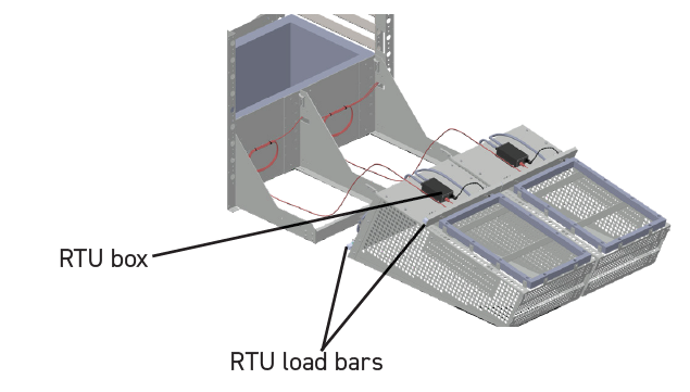
RTU Load Bars:
- Load cells (show the locations of the bars and mounting hardware).
- Ensure that cables are routed as is on the system to prevent cables from being cut on the metal work or accessible to the cattle (must use cable ties).
Paint Spray Line:
- Is routed from the spray system to each position and transports the marking dye from the tank to the spray nozzle on the position.
Data Cable:
- Transfers weight and EID data to the DAQ panel.
- Same as a regular Ethernet cable (CAT5 cable).
- Must be installed as shown on system to prevent cables from rubbing or animals from eating (must use cable ties).
DAQ Panel:
- A transmitter that gathers weight data from RTU boxes and sends it wirelessly to the data hub.
- The panel has two antennas located on the top of the unit. The longer of the two antenna is the unit’s radio antenna and the smaller of the two antenna is the GPS antenna. When replacing the panel make sure to replace the antennas.
- Has a simple 20 mm 6amp glass tube fuse inside to protect the panel from shorts caused by damaged cables or other power issues. If the panel goes down check and make sure this fuse is not blown, if it is, there is probably another issue (e.g., a damaged cable. DAQ panel
- shorts in the data cable caused by cattle, vermin, or other physical damage
will cause this fuse to fail). - The lights flashing above the individual channels indicate whether the
channel is actively collecting data. If it stops, it means the data is not being
collected because the RTU is down or the cable is damaged/unplugged. - The orange light flashing on a 0.5 second interval on the bottom of the
panel indicates that the panel is collecting/transmitting data and
functioning properly. This does not necessarily mean that data is being
collected at the computer, but it does indicate that the panel is working. If
the light is off or is not flashing on a 0.5 second interval, the panel is in
error. This will also show up as red bars on the DAQ software. - The solid green light indicates that we have GPS connection.
- If the panel goes down and the fuse is good, then the panel must be
replaced. We send replacements and shipping documents for the return of
the faulty panel. - The In-Pen Weighing Position DAQ panel is interchangeable with the FI DAQ panel.
Power Supply:
- Provides power to the entire system, scales and all.
- Waterproof and non-serviceable.
- If it fails, it must be replaced.
- Show connection to panel, as well as show connection to the power receptacle.
Spray assembly: (pumps, paint, lines, push/pull connectors).
- The system is used to mark sick animals or animals that have come up to market weight.
- Mounted beside the panel post and has a tank and pumps to move dye to the positions
- The spray lines are connected with push pull connectors. The one on the scale end is a check valve to retain head pressure (show the customer how to connect and disconnect the fitting).
7.2 Vytelle Computer
Data Hub:
- Collects data from DAQ8000 panels and makes it available to the computer where, during trials, it is stored and then sent to out and saved on our servers in Canada via the
internet connection. - Non-serviceable. if we have any issued, we replace the unit.
- Power light located on the bottom of the unit.
- Usually secured with hook and loop tape to the side of the computer of in a
location to provide better communication with the DAQ panels. - Must be connected to a USB 3.0 port on the computer. this port provides
the correct amount of power to run the data hub.
Computer:
- Stores the data collected by the Data hub.
- Has the DAQ software to interact with the system.
- Data displayed in the reports on the DAQ software is from the previous days data.
- Software uploads the days data to the Vytelle servers every morning at 12 a.m. MST.
Vytelle Servers:
Stores data from our systems around the world.
7.3 System Testing and Maintenance
Customer Toolbox
- Contains everything needed to service a Vytelle SENSE system.
- Spare items can be requested to replace the consumable items such as pigtails and spade connector ends.
Test Wand & Spray Wand:
- Kept in customer toolbox.
- Is used to test the read range (distance at which tags can be read by the antenna) and the spray system by forcing the system to spray.
- Can be used to prime the spray system.
- It has an EID tag installed in the cap that is programmed to make the system beep whenever it is read in one of the bunks.
- This shows that you have the correct read range in the bunk if it is beeping on a 1 second interval when placed tag up inside the trough.
- If the beeps have long gaps in between that shows that the bunk in question is having poor read range issues or the bunk is not reading tags consistently and service is required.
Calibration:
- Is used to verify the scales are weighing correctly.
- Is only done after replacing a DAQ panel (i.e., calibrate all RTUs attached to that panel), replacing an individual RTU, or before starting a trial.
- This can be done on individual scales, on a panel, or pen basis, or on the system as a whole.
- Both supplied calibration weights must be used to calibrate the system.
- To calibrate, put the supplied weights (100 lb total) onto the scale and then to insert the test wand into the same position, making sure not to touch or lean on the scale, wait for 10-15 consistent beeps. Once you have had a consistent 10-15 beeps, you can remove the beep wand and the weight and repeat the process in every In-Pen Weighing Position that needs calibration. Once all the positions have had the weight installed for 10-15 beeps you can then note the time and weight used to calibrate on the trial notes software or in the pre-trial checklist.
Scale Tare/Re-Tare:
- Is used to set the zero point for the scale.
- This must be done after the scale calibration.
- This is done by emptying the bunks and leaving them empty for at least 10 minutes and then noting the time they were emptied on trial notes or pretrial checklist.
Troubleshooting:
- When troubleshooting EID read issues start from the antenna and work back to DAQ8000 panel.
- When troubleshooting weight issues start at the RTU and work back to the DAQ8000 panel.
- Rule out components one at a time (i.e., is the antenna good? Yes? Check the load bar assembly, is it working? Yes? Check the data cable, is it intact? Yes? Check the DAQ8000 panel, is it working? No? Replace the panel, etc.).
7.4 Software
DAQ Dashboard:
- Displays live In-Pen Weighing Position weights.
- Shows action items and system status in top right. Under the Vytelle logo.
- Has a list of programs.
- Trial info button on bottom right.
Action Items:
- Notification of required system service that lists specific tasks that need to be completed on the In-Pen Weighing Position equipment.
- Located under “System Tools”.
- Explain completion of action item (i.e., checking complete box/entering username & password).
- Action items are how we communicate for non-emergency service items because it updates once a day at 6AM MST (when system uploads data to our servers).
- Support is going to/may have already sent a user access agreement form for usernames and passwords. We need a signed copy every time a person is added/removed from the system.
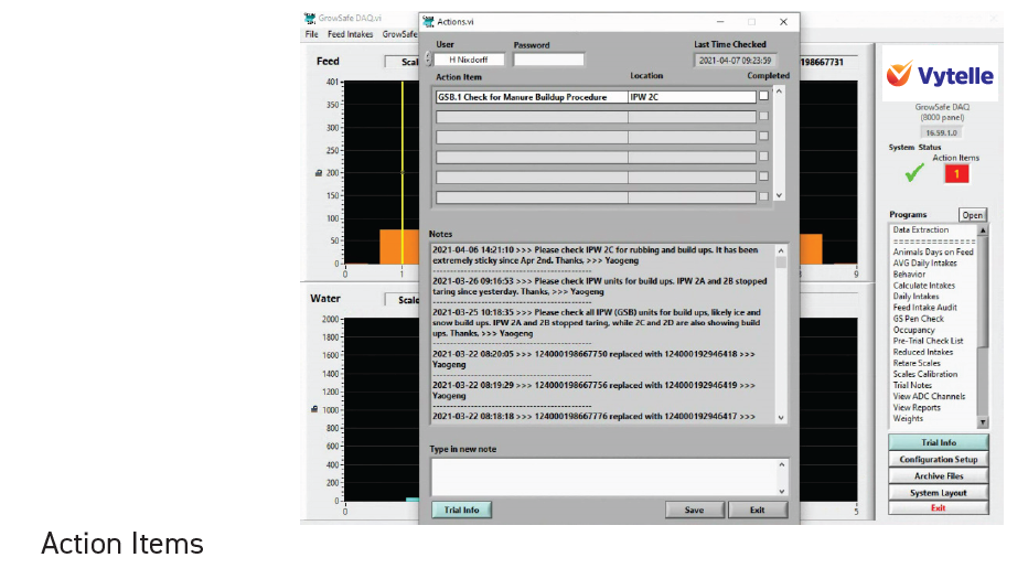
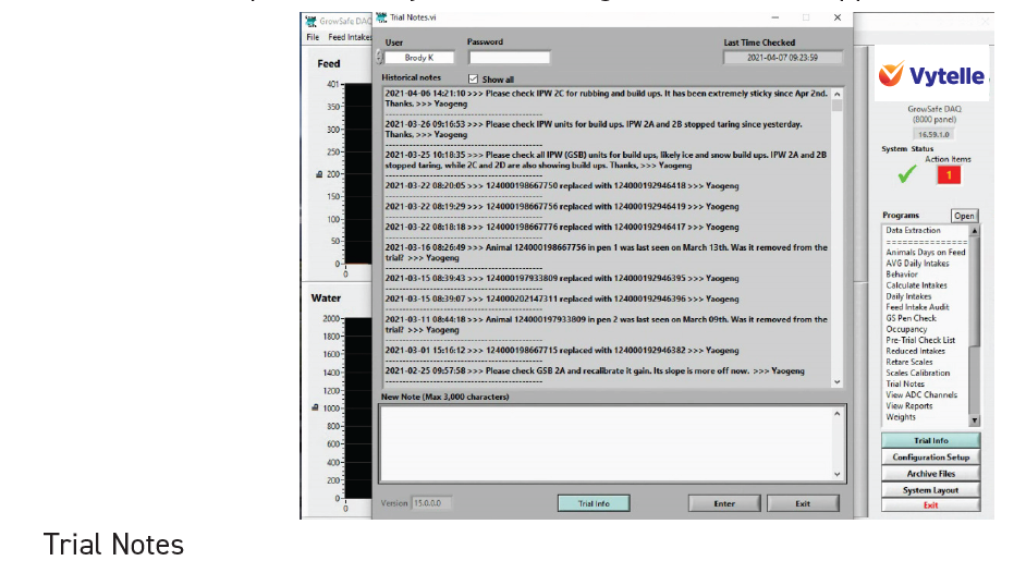
Trial Notes:
- Explain how action items are different from trial notes i.e., action items are notices of required service (change RTU’s, over/under feeding bunks, check rubbing, clean out under scale, etc..) trial notes are for all other non-emergency communication i.e., calibration and tare information, tag change, or animal removal.
- Trial notes show the time the system was last checked by support in the top right-hand corner if it does not update when you are running a trial contact support.
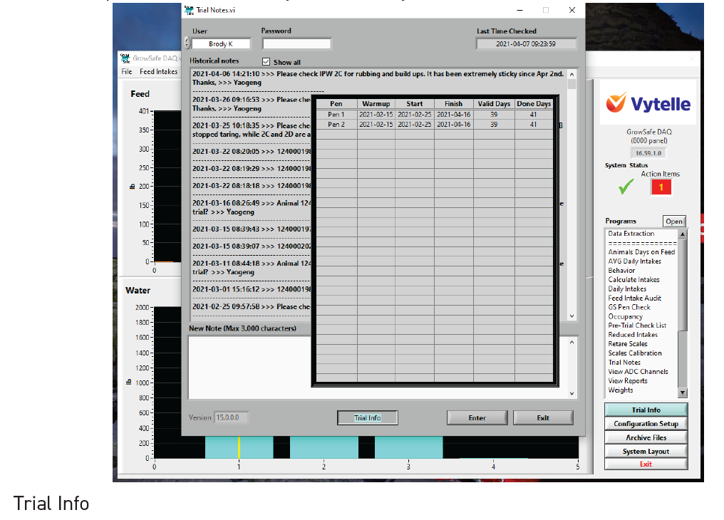
Trial Info:
- Click and hold to see your current trial information.
- Shows pen location, valid days vs. done days
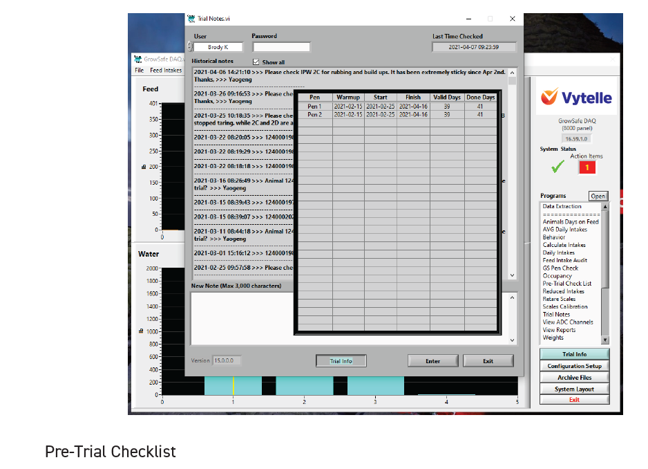
7.5 Pre-Trial Checklist
Fill out a checklist with the customer and save as TEST in the notes section.
- To be done prior to starting a trial.
- Feed intake trials should last 70 days with a minimum valid day count of 35.
- RFI trials should last 50 days with a minimum valid day count of 35.
- If you are running both Feed Intake Nodes and In-Pen Weighing Positions, you must go with the trial length of the Feed Intake Nodes.
- Both trials need to have 5 days in the beginning and 5 days at the end with one valid day for the trial to qualify.
- Show the action item PDF for filling out the pretrial checklist.
- Trials need to have a minimum 14-day warm-up. That is with animals on the system and EID tags in the animal’s ears. This is to make sure the system is working correctly, help figure out herd hierarchy, and make sure the animals are eating/drinking normally from the system.
- The pens on trial must be highlighted blue or they are not selected.
- If animals are removed from the trial during the trial. Let us know in trial notes so we can archive the file for that animal.
- If an EID tag is changed, let us know the old and new tag number so we can combine the info for those tags.
- Never re-use tags that have previously been registered on a Vytelle SENSE system, as this will merge previous animal data with new data.
- Plan for your first trial to go longer than average. There is a learning/adjustment period while we work to get the system working accurately.
7.6 Reports to Check Daily
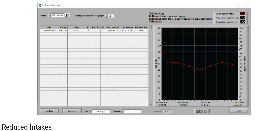
Reduced Intakes:
- Make sure to check a few days after beginning a trial. You will be able to easily find animals who are not adjusting to the system, animals with missing tags or animals that have been miss-penned.
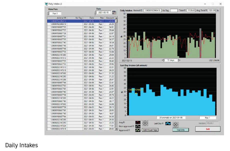
Daily Intakes:
- Monitor during warm up specially to make sure the number of tags match the number of animals on trial.
- Make sure the number of animals in the pens are correct.
- You can edit visual tags here (data is stored with the EID tag number and not the visual tag number).
- Graph colors: green = valid intakes grey = invalid intakes (hardware related).
8. FINALIZING INSTALLATION
The final step in the installation of a Vytelle SENSE system is to complete the commissioning checklist, have it signed off by the customer, and sending it to you your Field Service Coordinator. This signifies that the instillation was successfully completed and approved by the customer. Make sure to check off all that applies to your specific installation. Add any important notes on any issues you encountered as well as anything the may yet need to be completed (e.g., fencing around the system etc.). Make sure to document the serial numbers of any spare equipment that was supplied for use by the TSRs during potential future troubleshooting (i.e., Parts in Trust). If there were any significant changes to the site layout due to unforeseen circumstances, please notify your Field Service Coordinator to have the drawing updated to reflect the current site layout.
Appendix I: Troubleshooting a Problem Position
9. APPENDIX I: TROUBLESHOOTING A PROBLEM NODE
Optimized for print with Google Chrome browser.