8000 Feed Intake Node: Unloading And Assembly Instructions
Field Services - Technical Manuals
INTRODUCTION
This instruction manual describes the unloading, assembly, and start-up requirements for Feed Intake Nodes.
Use the Table of Contents to guide you to specific areas. Retain this instruction for future reference.
CAREFULLY READ ALL THE MATERIAL PROVIDED BEFORE ATTEMPTING TO UNLOAD, ASSEMBLE, OR USE THE SYSTEM.
SYSTEM OVERVIEW
FEED INTAKE NODE
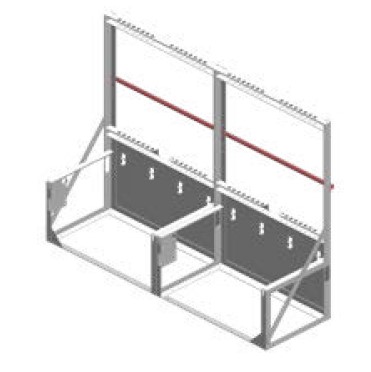
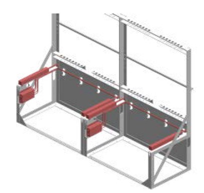
Vytelle’s Feed Intake Nodes measure individual feed intake and feeding behavior and can be used in conjunction with the In-Pen Weighing Positions to provide a more accurate depiction of an individual animal’s efficiency. The Vytelle SENSE™ system replaces the traditional feed bunk with a set of individual scale-mounted feed troughs to enable measurement of individual animal consumption.
The Feed Intake Nodes require cattle to lower their heads into the feed trough to collect their RFID information as they eat. At this point, the trough scale records a feeding event collects a weight reading of how much feed is in the bunk at the start of the feeding event. This number is compared to the scale reading when the feeding event is over (i.e., animal’s head is no longer in the bunk) and the difference is attributed to that animal’s consumption. The Feed Intake Nodes are installed to fit the existing pen layout at a customer site. Feed Intake Nodes can be installed singly, in pairs, or in larger blocks. An individual DAQ panel can support a maximum of eight nodes.
VYTELLE DATA HUB AND COMPUTER
All Vytelle SENSE systems send their collected data to a central computer that is usually kept in an office or room close to the system itself. The computer comes pre-installed with Vytelle Insight™ Software and is paired with a Data Hub, which work together to collect and display the data from the associated Vytelle SENSE system(s). The data hub collects the data wirelessly from the DAQ panels on the system(s) and stores it locally in a database file on the computer. This data is also uploaded to Vytelle’s servers in Alberta, Canada every morning at 6AM MST, where it is backed up and can be accessed and monitored by Vytelle’s Technical Service Representatives (TSR) team.
TABLE OF CONTENTS
1 Safety
1.1 Signal Words
2 General Safety
2.1 Safe Lifting
3 Feed Intake Node Definitions
3.1 Feed Intake Node Hardware
3.2 Computer System
4 Unloading the Equipment
4.1 Moving System Around Site
4.2 Breaking Down Pallets
4.3 Disposing of Shipping Dunnage and Other Materials
5 Assembling and Installing the Feed Intake System
5.1 Installing the Data Hub
5.2 Vytelle Computer System
5.3 Carrying Out the Internet Speed Test
5.4 Feed Intake Node Hardware
5.4.1 Installing the Frames and Panel Post
5.4.2 Installing the Horizontal Neck Bars
5.4.3 Installing the RTUs
5.4.4 Installing the Node Labels
5.4.5 Installing the Data Cables
5.4.6 Data Cable Management
5.4.7 Installing the DAQ Panel, DAQ Panel Cover, and Power Supply
5.4.8 Installing the Spill Protectors
5.4.9 Installing the Vertical Neck Bars
5.4.10 Installing the Troughs
5.4.11 Powering Up the System
5.5 DAQ Dashboard & Adding DAQ Panels
5.5.1 Adding Test Wands
5.5.2 Tuning Antennas & Calibration
5.5.3 Verifying Calibrations & Taring
6 General Installation Troubleshooting
6.1 No Audible Beep with Test Wand
6.2 Calibration Baseline Does Not Return to Zero or is Not Clean
6.3 DAQ Panel Does Not Display Correct Lights
6.3.1 DAQ Panel Will Not Power On
6.3.2 No GPS or Radio Lights on the DAQ Panel
6.3.3 DAQ Software is Not Receiving Data from
DAQ Panel(s)
6.3.4 No Blinking Indicator Light at One or More
Channels
7 Customer Training Points
7.1 Feed Intake System
7.2 Vytelle Computer
7.3 System Testing and Maintenance
7.4 Software
7.5 Pre-Trial Checklist
7.6 Reports to Check Daily
8 Finalizing Installation
Appendix I: Troubleshooting a Problem Node
1. SAFETY
1.1 SIGNAL WORDS
Three signal words; DANGER, WARNING, and CAUTION, are used to alert you to hazardous situations. The appropriate signal word for each situation has been selected using the following guidelines.
DANGER Indicates imminently hazardous situations that, if not avoided, with result in death or serious injury.
WARNING Indicates a potential hazardous situation that, if not avoided, could result in death or serious injury. It may also be an alert against unsafe practiced.
CAUTION Indicates a potentially hazardous situation that, if not avoided, may result in minor, or moderate injury. If may be used to alert against unsafe practices.
2. GENERAL SAFETY
CAUTION
The following are general work safety precautions that should be a part of your operating procedure for all Vytelle work sites.
Protect yourself:
• When assembling, operating, and servicing any Vytelle SENSE system, wear all the protective clothing and personal safety devices that COULD be necessary for the job at hand. Do not take chances.
You may require:
• Hearing protection
• Respirator or dust mask
• Wet weather gear
• Work gloves
• Safety glasses
• CSA approved protective footwear
• Hard hat and reflective vest (depending on site requirements)
General safety considerations:
• Keep children away from equipment and machinery.
• Locate a first aid kit for use in case of emergencies.
• Be cautious around machinery and other equipment, always keep eye contact with machine operators when working and maneuvering around mobile equipment.
• Keep work site clean of obstructions, empty pallets, shipping dunnage, plastic wrap, empty boxes. These items might create tripping hazards.
• Keep work area well lit.
• Be cautious in cold or wet weather as it might make for slippery conditions.
• Be careful working with and around Vytelle SENSE system equipment as sharp metal edges can cause injury.
• Keep all tool shields in place. Never remove or alter safety equipment. Ensure all tools are in proper working order prior to system assembly.
• Identify and avoid pinch points when maneuvering Vytelle SENSE system equipment during unloading or assembly/installation.
2.1 SAFE LIFTING
• Do not attempt to lift by bending forward. Bend your hips and knees to squat down to your load, keep it close to your body, and straighten your legs to lift.
• Never lift a heavy object above shoulder level.
• Avoid turning or twisting your body while lifting or holding a heavy object.
3. FEED INTAKE NODE DEFINITIONS
3.1 FEED INTAKE NODE HARDWARE
Each numbered term is represented on a set of figure drawings below the definition list for clarity.
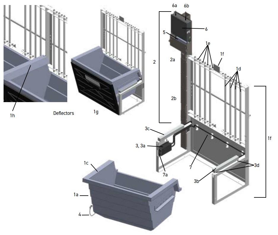
1. Feed Intake Node – The assembled Feed Intake Node unit, including the following components:
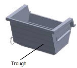
a. Trough – grey injection moulded plastic feed trough that contains the antenna used to read the EID tag of the animal feeding. Has metal brackets that position the trough on the RTU load bars (scales).
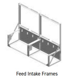
b. Frame – anchors the Feed Intake node to the ground and provides a barrier between the animals that feed from the node and the feed alley.
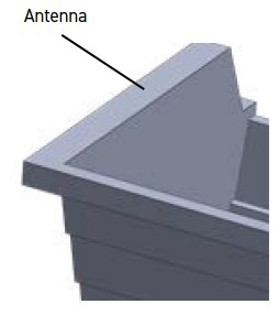
c. RFID antenna – double 14AWG stranded antenna wire that is secured in the upper lip of the trough which reads RFID tag numbers as animals lower their heads into the trough to feed. Secured in trough with foam backing rod.
d. Neck bars (vertical & horizontal) – prevent more than one animal from accessing the position at a time. Can be adjusted based on the size of animals being tested.
e. Neck bar pins – removable pins that secure the neck bars in place.
f. Label – labels each node for clarity and consistency during service and troubleshooting (lowest number corresponds with lowest channel letter in panel).
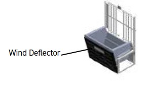
g. Wind deflector – Helps to prevent buffeting of the bunk in outdoor environments, which reduces vibration and noise.
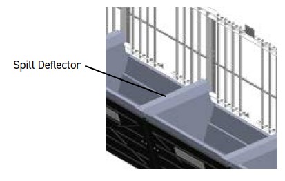
h. Spill deflector – Usually installed between adjacent troughs. Helps to prevent feed from accumulating on or near the RTU load bars and gives some protection from the elements.
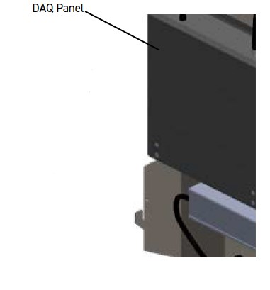
2. Panel Post – holds the DAQ panel, power supply, and houses data cables.
a. DAQ panel cover – hinged cover designed to protect data cables and power supply from animals and the elements.
b. Panel post cover – bolted cover that protects the data cables stored in the panel post from animals and the elements.
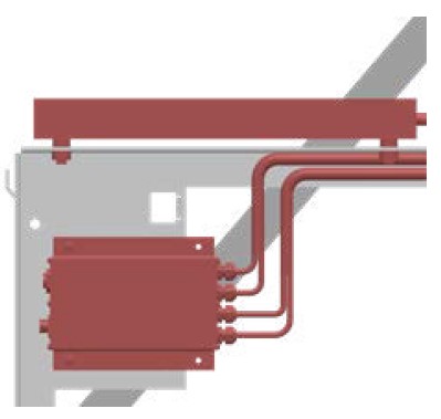
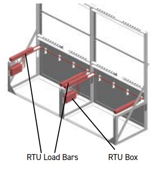
3. RTU – the scale that does the weighing of feed. Consists of an RTU box and four load cells; two load cells per bar; two bars per set. Also transmits RFID data to the DAQ panel.
a. RTU box – the device that collects the RFID data from the antenna and weight information from the load cells in the load bars.
i. RFID antenna port – connection point for the RFID antenna.
ii. Data cable port – connection point for the data cable.
b. Long bar – the bar attached to the RTU box that has longer cabling.
c. Short bar – the bar attached to the RTU box that has shorter cabling.
d. RTU spacers – rubber mounts that support the RTU bars on the frame. These spacers aid in minimizing the effects of vibrations on the system (instructions are supplied with the RTUs).
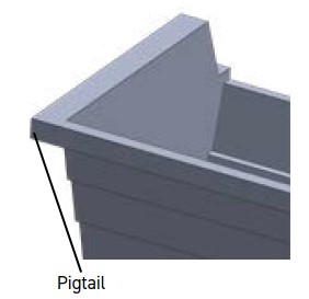
4. Pigtail – connects the RFID antenna in the trough to the RTU box. Located on the side of the trough under a black plastic cover that is secured with a wing nut.
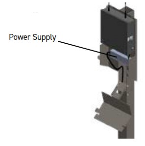
5. Power supply – provides power to the system. Can be hooked to either 110vac or 240vac power.
6. DAQ panel – Transmits weight and RFID data to the data hub.
a. GPS antenna – provides GPS radio connectivity to satellites.
b. Radio antenna – provides connectivity for data transmission between DAQ panel and data hub.
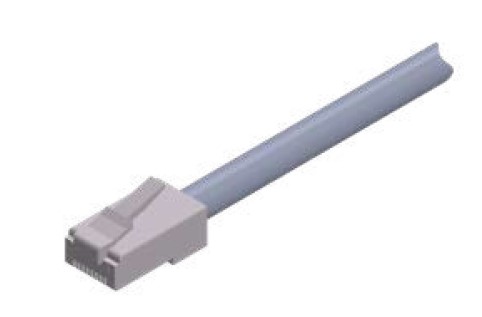
7. Data cable – transmits data from the RTU box to the DAQ panel. Identical to an RJ45 connector on a standard ethernet cable.
a. Watertight fitting – a watertight fitting on one side of the data cable that is twisted on to the connection port at the RTU box to provide added protection from inclement weather for outdoor systems and to provide added strength at this connection point.
3.2 COMPUTER SYSTEM
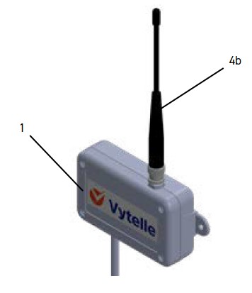
1. Vytelle computer – contains the DAQ software and records the data collected by the system.
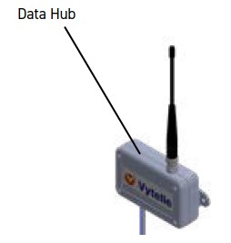
2. Data hub – small black device, connected to the computer via USB cable and to a radio antenna that provides connection to the DAQ panels on the system in the field.
3. DAQ software – contains the programs Vytelle support teams use to interact with the system, a way to view and interpret its collected data. Contains processes used to calibrate and set up the system for a trial.
4. Radio antenna: used to connect the data hub and DAQ panels in the field. The antenna location and condition are important. Operating the system in low lying areas or terrain, under power lines or bridges, inside or through a metal framed building can severely reduce the range on the unit. Mountains can also reduce the range of the unit. There are two antenna options:
a. YAGI antenna – in areas where transmission or reception is poor, some improvement may be obtained by ensuring that an antenna is mounted externally on the building that houses the Vytelle computer. Moving a few metres in another direction or moving to a higher elevation may also improve communications. This antenna has more power to get through some obstacles such as tin roofs, concrete walls, or other environmental obstacles.
b. Rubber duck antenna – simple small antenna mounted on the data hub itself inside of the office with a Vytelle computer. Generally, this antenna style is adequate for systems that are located within a clear sight line and relatively close proximity to the Vytelle computer office. This is the same antenna version used on the DAQ panels.
4. UNLOADING THE EQUIPMENT
4.1 MOVING SYSTEM AROUND SITE
DANGER Mobile equipment should never be operated without the proper training.
CAUTION To avoid injury to bystanders from being struct by machinery, do NOT allow people to stand in the unloading area at any time.
WARNING Use of inadequate equipment may result in equipment damage, injury and or death.
IMPORTANT: Palletised Feed Intake Node components should be moved on or around site by the customer. If required, mobile equipment (tractor, skid steer, fork-lift) should be provided by the customer to move the pallets to their final location. Such equipment should only be operated by designated personnel, i.e., trained operators, to ensure safety of those unloading the system.
1. Use forklift or skid steer to unload each pallet from the delivery trailer.
2. Move the palletised components as close to the delivery site as possible.
a. If installation of the system is not going to occur immediately, ensure that the system components are stored out of the elements where possible until such a time that they are to be installed.
b. Ensure that pallets are unloaded onto a level surface.
3. Check Feed Intake components for any external shipping damage.
4.2 BREAKING DOWN PALLETS
1. Remove straps holding units to pallets.
a. Be aware that items may have shifted during shipping resulting in imbalance or slipping once straps are removed.
2. Remove any loose items packaged with Feed Intake Nodes and set these aside.
3. Inspect the unpacked shipment for missing components by comparing with the shipping manifest.
4. Collect all shipping materials (straps, bolts, plastic, etc.).
4.3 DISPOSING OF SHIPPING DUNNAGE AND OTHER MATERIALS
After pallets have been unpacked, collect all shipping waste to a central location. Contact the customer or site manager to discuss their preferred method of disposal for these items and dispose of dunnage accordingly.
IMPORTANT: Ensure ALL Vytelle SENSE system scrap metal is collected from the customer site prior to technician departure.
FEED INTAKE NODE
5. ASSEMBLING AND INSTALLING THE FEED INTAKE NODES
5.1 INSTALLING THE DATA HUB
1. Obtain the supplied data hub from the shipped Vytelle SENSE system equipment and twist the supplied radio antenna onto the top of the data hub.
2. Remove the protective tape on one of the adhesive sides of the supplied Velcro tape and apply it to the back of the data hub.
3. Locate the designated Vytelle computer at the site (generally in an office or building near the Vytelle SENSE system but may have been sent with the system shipment) and install the data hub on the side of the computer tower or the wall above the computer.
a. For best placement, install the data hub near the Vytelle computer whenever possible.
4. Connect the USB cable to the relevant port on the data hub and connect the other end of the cable to a USB 3.0 port on the Vytelle computer, a power light should be displayed once this cable is plugged in.
a. USB 3.0 ports are identified as blue ports versus the standard black or white ports that represent USB 2.0.
5. The site layout determines what type of radio antennas that are provided for use with the system. There are two types of radio antennas provided with the system: a short-range “Rubber Ducky” antenna and a long-range, directional “Yagi” antenna.
a. If your system has been provided with the short-range rubber ducky antenna, install it onto the port on the top of the data hub.
b. If your system has been provided with the long-range Yagi antenna and mount, you will have to install the antenna mount and antenna higher up on the building so it can be aimed at the DAQ panels. Route the co-ax cable into the building and plug the other end of the cable onto the data hub.
5.2 VYTELLE COMPUTER SYSTEM
IMPORTANT: The customer is responsible for the installation of the Vytelle computer and for setting up the computer’s log-in information. When you arrive on site, be sure to verify that the computer installation has occurred or will be occurring, as soon as possible. Log-in information must be communicated to the Technical Support team (support@vytelle.com) and the computer must be connected to the internet to allow mandatory installation updates to be completed by the IT Services team. It is important that as soon as the computer has been connected to the internet you contact your Field Service Coordinator or Vytelle IT (it@vytelle.com) with your site information to make sure that the computer and the software are configured correctly. The Technical Support and IT Services teams that remotely monitor and maintain the system access the customer’s computer through a program called LogMeIn, which requires an internet connection to be fully functional.
5.3 CARRYING OUT THE INTERNET SPEED TEST
1. Open a web browser on the Vytelle computer and navigate to the Google home page.
2. Type ‘speed test’ into the search bar and click the blue ‘Run Speed Test’ button on the first search result.
3. Allow the test to run and record the resulting download and upload speeds on the post-installation checklist.
5.4 FEED INTAKE NODE HARDWARE
IMPORTANT: Always refer to the site layout drawings prior to beginning installation of any Vytelle SENSE system equipment. Ensure all installations match the provided site layout. Contact your Vytelle Field Service Coordinator PRIOR to installing any equipment if there are discrepancies between the intended layout and what is possible at the site. All hardware used for Feed Intake Node assembly can be found in the *FIMWKIT* hardware bags provided with your equipment.
5.4.1 INSTALLING THE FRAMES AND PANEL POST
1. Arrange the frames on the outside of the pen on the supplied level concrete following the site layout and place a “FIMWKIT” hardware bag at each frame.
2. Divide all the vertical neck bars evenly with all the frames (eight bars per frame). Do the same with the horizontal neck bars (one bar per frame).
3. Bolt together frames that are side-by-side using four- 3/8” (10mm) x 1” (25mm) Grade 5 hex bolts & 3/8” (10mm) nuts. Make sure to use two 3/8” (10mm) washers per bolt, one on either side.
Adjacent frames bolted together.
4. Consult the site layout to verify where the panel post is to be installed and move it into position.
5. Bolt the panel post to the correct frame (or set of frames) using three of the same 3/8” (10mm) x 1” (25mm) Grade 5 hex bolts and 3/8” (10mm) washers and lock nuts.
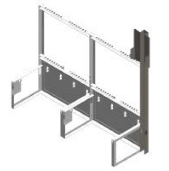
Panel post bolted to FI frame.
6. Square the frames to the pen and use a measuring tape to verify frame placement relative to any surrounding fencing. If there are concrete bunks adjacent to the system you can square the system to those. Use your own discretion.
a. Frames should be placed such that the space between the block of frames and the pen fencing is minimized to ensure the integrity of the pen is not compromised. If this is not possible following the site layout instructions, consult with the site manager and/or a Vytelle contact to reach an alternative solution.
b. Any major gaps left between the frames and the fencing will have to be filled by the customer to prevent animal access. Discuss this with the site manager to make sure the task is completed.
7. Check that each frame is level in its current position. In the event a frame is not level, slide the supplied shim washers under the frame’s four corners to level it. Ensure that the shims are centered around the anchoring holes.
a. Check the level on all four sides of each individual frame before moving on. This includes the RTU mounting arms on each side of the frame.
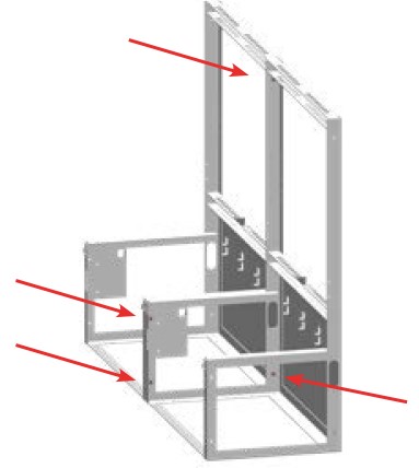
8. Once all frames are level and square, use a hammer drill to drill a 3/8” (10mm) x 4-6” (100mm – 150mm) hole at each of the four corners of the frame and then hammer in a 3/8” (10mm) x 3” (75mm) cement anchor at each corner. *do not use the holes on the flat strap on the feed alley side of the frame* You will use four cement anchors per frame. Tighten the anchor nuts after all the anchors are installed.
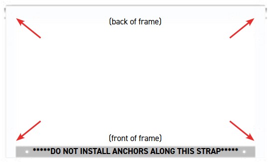
View of frame from above. Arrows point to possible anchor locations.
9. Verify that each frame remained level during the anchoring process.
a. If any component is not level upon re-checking, release the cement anchors on that component and modify the number of shims supporting the component such that the component is level and then re-install the anchor nut and verify the component remains level. In the event you cannot level the component with shims, you may have to re-anchor the component by drilling a new pilot hole and re-anchoring the component. Before attempting to re-anchor the component, ensure it is level and square. If you must move the frame or the panel post, be sure to re-measure to ensure all components are distanced appropriately before moving on.
10. Find the triangular corner brackets and the long end brackets (has one pointed end and three holes) that were supplied with the feed intake frames and place one of each bracket type at each end frame along with three 3/8” (10mm) x 1” (25mm) Grade 5 hex bolt, nuts, six 3/8” (10mm) washers, and one 3/8” (10mm) x 3” (75mm) concrete anchor.
a. For example: if there are eight frames in groups of two, you will require eight corner brackets and eight straps. If you have eight frames in one group, you will require two corner brackets and two straps.
11. Put the triangular corner bracket into position at the base of the end frame along the front strap. The flat triangular face of the bracket should face out toward the feed alley
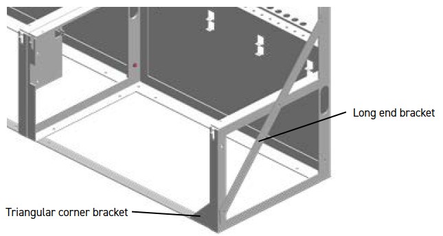
Close-up view of long end bracket and triangular corner bracket in place.
12. Line up the hole on the pointed side of the end bracket with the same hole on the side of the end frame that will be used to secure the triangular corner bracket (the triangular corner bracket will be secure on the inside of the frame, while the end bracket will be installed on the outside). Use a bolt, washer, and nut to secure both the triangular corner bracket and the end bracket to the frame at this hole.
13. Install a concrete anchor at the other side of the triangular corner bracket by lining up the remaining hole with the provided hole along the front strap of the frame.
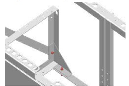
Close-up view of triangular corner bracket installation.
14. Line up the other two holes on the end bracket with the two matching holes on the frame and secure the bracket using the remaining 3/8” (10mm) hardware.
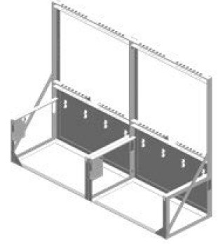
Long end brackets and triangular corner brackets installed on the FI system.
15. After securing the bracket, use a spirit level to check that the vertical arm is not bent in toward the trough. If it is, loosen the concrete anchor and install shim washers to achieve level.
5.4.2 INSTALLING THE HORIZONTAL NECK BARS
1. The horizontal neck bars are the long bars with the flat tabs welded on each end. These tabs have holes drilled for mounting on the frames. The bars are mounted on the rear (animal side) of the frame and are to be adjusted to the size of cattle being used on the system.
2. Locate the parts bag labeled “Horizontal Neck Bars” (inside the Feed Intake Node hardware bag and utilizes the same 3/8” (10mm) hardware that was used to join the frames together).
3. The default positioning for the horizontal neck bar is to be installed on the animal side of the frame one hole from the top hole that is drilled on the angle iron on the frame. This position generally works with most sizes of cattle. Secure all four bolts on the bars for all Feed Intake frames.
5.4.3 INSTALLING THE RTUS
1. Install one RTU on each frame using the provided four ½” (13mm) bolts, washers, four large spacers, and four small spacers per RTU. Use the provided instructions (packaged with the RTU’s) to install the RTU load bar on the frame. The bar with the longer cabling should be installed on the right mounting arm (when facing the frame from the feed alley), while the bar with the shorter cable will be installed on the left mounting arm.
a. When mounting RTUs, care should be taken not to overtighten bolts, as this can crush the spacers and cause the load bar to touch the frame, this will lead to inaccurate weight readings. Each bar of the RTU should be installed such that the cabling is oriented toward the back of the frame.
b. As shown in the provided RTU instructions, thread the washer and small spacer onto the bolt and insert the bolt up from the bottom of the frame. Thread the long spacer onto the exposed bolt on the top of the frame and then screw the bolt into the load bar.
2. Route the cabling on the long bar along the back of the frame on the top row of designated cut outs. Cabling should be secured to the frame with cable ties and not interfere with the trough when installed.
RTUs, horizontal neck bars, and vertical neck bars installed.
3. Use the two supplied ¼” (6mm) x ¾” (20mm) hex-head bolts, four ¼” (6mm) washers, and two ¼” (6mm) lock nuts to secure the RTU box to the FI frame on the left side (under the RTU’s short bar). Ensure that the data cable plug is facing outward when installed and the product and serial numbers are readable.
5.4.4 INSTALLING THE NODE LABELS
1. Locate the node number labels supplied with the frames and install them following the site layout using the two supplied ¼” (6mm) x ¾” (20mm) hex head bolts, four ¼” (6mm) washers, and two ¼” (6mm) lock nuts per node. The number plates are mounted on the top of the frames using the supplied holes.
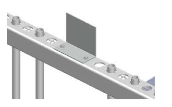
Node label installed on the Feed Intake Node frame, view from the back of the frame to show bolts and washers installed. The flat face of the plate should be facing the feed alley side of the frame.
5.4.5 INSTALLING THE DATA CABLES
Collect the data cables for the system you are working on and distribute them to each of the frames you have installed, following the site layout. Ensure that the appropriate lengths are installed at the right nodes for ease of future servicing.
1. Following the site layout, connect the watertight end of each data cable to its respective RTU box. Be sure to secure the watertight fitting by twisting it to finger tight.
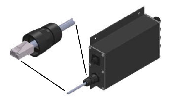
Watertight fitting on the data cable connected to the bottom port of the RTU box.
2. Once all cables are connected to their respective RTUs, label the other end of each with a marker according to their node.
Labelled end of the data cable that will be connected to the DAQ panel.
3. Run each cable through the cut outs on the frame into the panel post.
5.4.6 DATA CABLE MANAGEMENT
1. With all cables fully routed, begin securing the data cables with the supplied zip ties using the lower row of designated cut outs on the Feed Intake Node frame.
a. On the underside of the RTU mounting arms, zip tie the RTU cabling and node data cable together where possible. Ensure the RTU cabling is securely zip tied on to the Feed Intake Node frame on both the underside of the RTU mounting arms and along the back of the Feed Intake Node frame.
i. Securing cables properly prevents animal and pest-related wear on the cables and prevents cabling from being pinched or sheared while troughs are moved in or out of the frame.
2. Gather excess cable slack in the DAQ panel post and secure it neatly with a zip tie.
3. Once all cables are secured, install the panel post cover on the panel post using 3/8” (10mm) head thread forming screws on each side of the cover.
5.4.7 INSTALLING THE DAQ PANEL, DAQ PANEL COVER, AND POWER SUPPLY
1. Obtain one DAQ panel and record the address number listed inside of the door and the location you will be installing it in as you go (i.e., Panel #1 Address #: 4157D9E2; Panel #2 Address #: 4157D9A7; etc.).
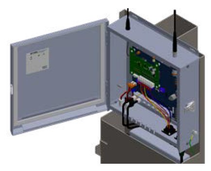
2. Screw in the GPS antenna and the radio antenna to the top side of the DAQ panel.
a. Depending on the site layout, a long-range Yagi radio antenna and mount may have been provided. Install the mount on the upper rear of the panel post and install the antenna so that it is pointed at the data hub.
3. Maneuver the cut-outs on the back of the DAQ panel onto the hooks on the panel post such that the DAQ panel is fully supported by the panel post.
4. Use two 3/16” (5mm) head self-tapping screws to secure the bottom of the DAQ panel onto the panel post.
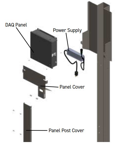
View of all panel post components that will be installed, including DAQ panel, power supply, panel cover, and panel post cover, along with the associated nuts, bolts, washers, and screws required for installation of these components.
5. Connect the data cables to the DAQ panel following the site layout.
a. IMPORTANT: Refer to and confirm with the site layout to confirm the placement of all installed cables before moving on.
6. Install the DAQ panel cover on the panel post using the two supplied ¼” (6mm) x ¾” (20mm) hex head bolts, four ¼” (6mm) washers, and two ¼” (6mm) lock nuts, as shown. Nuts should be installed such that they are loose enough to allow the door to hinge into place.
Hinged panel cover installed on panel post.
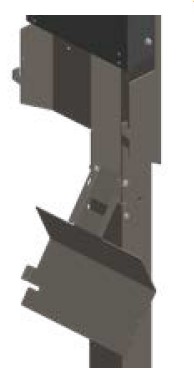
7. With the cover in the open position, install the rectangular power supply below the DAQ panel and above the recessed location for the power outlet using two 3/16” (5mm) head self-tapping screws. The DAQ panel plug end should be facing to the right when looking at the power supply mounted on the post.
a. Ensure the panel cover closes properly before moving on. If the cover is unable to close properly, move the power supply accordingly.
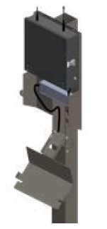
View of power supply installed on the panel post below the DAQ panel.
IMPORTANT: The customer is responsible for installing electrical at this point in the installation, communicate this requirement with the site manager or your site contact before moving on. Be sure to establish the correct position for the power outlet on the system. The receptacle is to be located inside the DAQ panel post and the routing of conduit cannot interfere with the scales or block the panel post covers. Power can be run in any of the following ways:
• Down from the top into the post.
• Along the fencing, into or along a horizontal fence post, and up into the post.
• Along the concrete pad and up into the DAQ panel post (modification of the panel post cover may be required).
5.4.8 INSTALLING THE SPILL PROTECTORS
1. Once the frames are installed and leveled, retrieve the long triangle spill protector mounts that were supplied with the Feed Intake Node frames and place one where every frame it is connected (i.e., if you have eight frames bolted together you will need seven brackets).
2. The bracket is bent to position it directly in the middle of the two frames using two mounting holes that are located above the RTU mounting location between the vertical neck bars, the bottom hole is slotted for adjustments.
3. Inside the Feed Intake Node hardware bag there is a pouch labelled “Spill Protector” with the hardware required to install the brackets.
4. Install the brackets with the flat bar facing up and away from the RTU mounting arms.
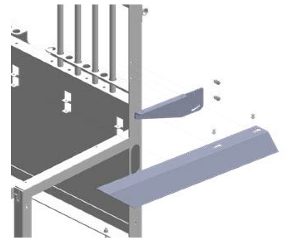
Expanded view of the spill deflector bracket and spill deflector installation on the Feed Intake Node frame including hardware required to install each component.
5. Once the brackets are installed, install the two carriage bolts with the two remaining washers inside the threaded holes on the bracket.
6. Slot the spill protectors onto the carriage bolts installed in the previous step. The protector can then be adjusted to ensure that they do not rub against the troughs.
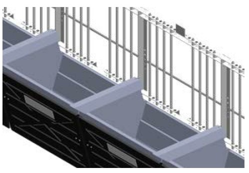
View of spill deflectors installed between adjacent Feed Intake Node frames.
5.4.9 INSTALLING THE VERTICAL NECK BARS
1. The vertical neck bars have holes drilled in the tops as connection points for the neck bar pins. The bars are installed by either feeding them in from the top or feeding them up into the top holes and down into the bottom holes and then locked in with a retaining clip.
2. The bars are to be installed such that they allow only one animal to fee from the trough at a time. If you see more then one animal feeding from one trough, make sure to narrow the gap by moving the neck bars in.
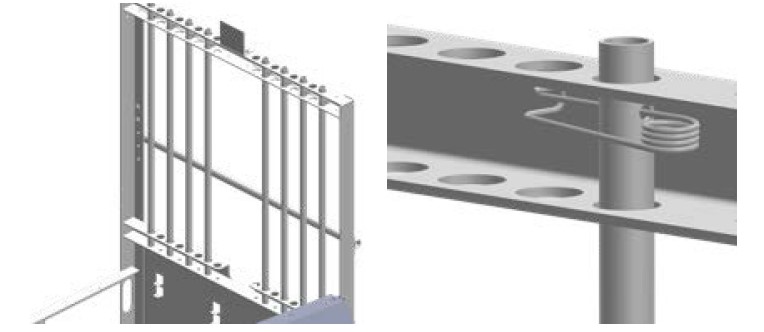
View of neck bars installed on the Feed Intake Node frame and close-up of the neck bar pin installed.
5.4.10 INSTALLING THE TROUGHS
1. Install one feed trough per Feed Intake Node frame, with the logo facing toward the feed alley, by sliding it into place over the RTU load bars.
a. Ensure that the trough does not contact anything but the RTU load bars. The trough should not rub on the cables, ground, spill protectors, or their brackets.
b. If the troughs rub on the spill protector mounts, you can remove the trough from the frame and bend the side walls of the trough in to prevent then from rubbing.
2. Verify that the trough is sitting on the RTU correctly by confirming that the trough supports are placed squarely on the RTU load bars (i.e., trough is fully in rest and not propped up on one side, trough supports are not set on the RTU at an angle, etc.).
3. Plug the trough’s pigtail into the RTU box and twist the plug fitting until finger tight. The 90-degree fitting on the pigtail should be pointing up. Not down or to the side.
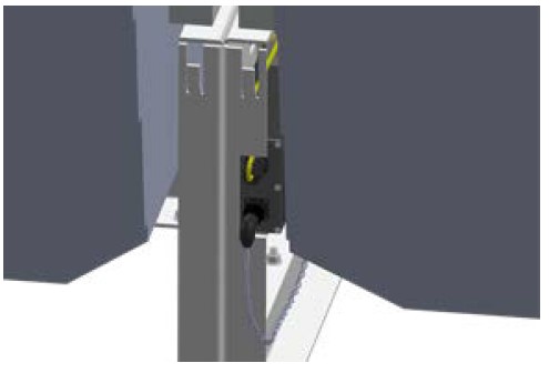
Close-up view of the pigtail and data cable plugged into the RTU box with the trough in place.
4. Slide the supplied wind deflectors into place in front of the trough such that the wind deflector is fully supported by the wind deflector cut outs.
5.4.11 POWERING UP THE SYSTEM
1. Once electrical is installed, plug the power supply into the electrical outlet and then plug the power supply into the DAQ panel. You should see lights appear on the DAQ panel to indicate that it is running.
2. Plug the other end of each data cable into the appropriate channel following the site layout
Data cables plugged into channel A and channel B.
5.5 DAQ DASHBOARD & ADDING DAQ PANELS
1. At this point you should have received word of the computer’s correct configuration. If not, contact your Field Service Coordinator to make sure that is has been completed.
2. The Vytelle computer is set up to auto-login and launch the DAQ software and Watchdog. If these two programs do not launch automatically, contact Vytelle IT (it@vytelle.com).
Watchdog and DAQ Dashboard software.
IMPORTANT: If you do not have a username and password with the credentials required to make system changes, you are unsure of your user credentials, or you are having any technical issues with the following steps, please contact your Field Service Coordinator to have the following tasks completed.
3. Click the “Configuration Setup” icon in the bottom right of the DAQ software Dashboard.
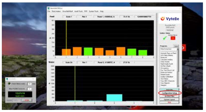
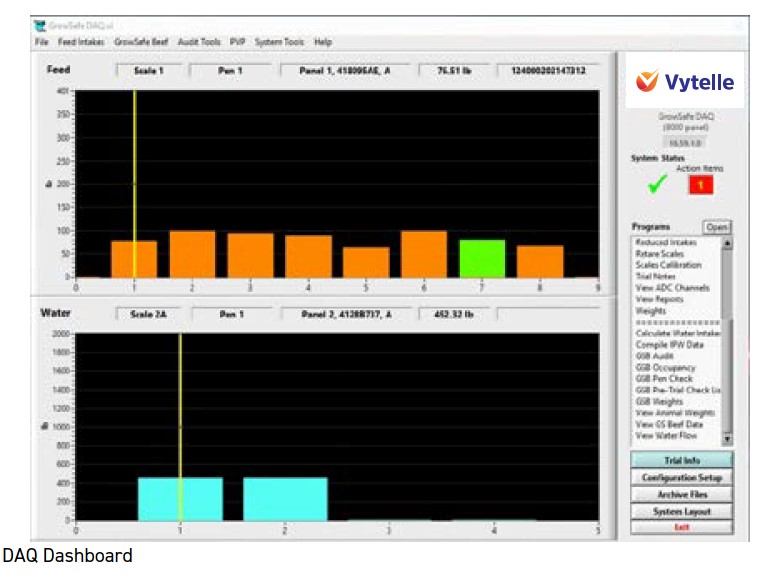
DAQ Dashboard home page.
4. Click the “Hardware” tab located in the top left of the Configuration window.
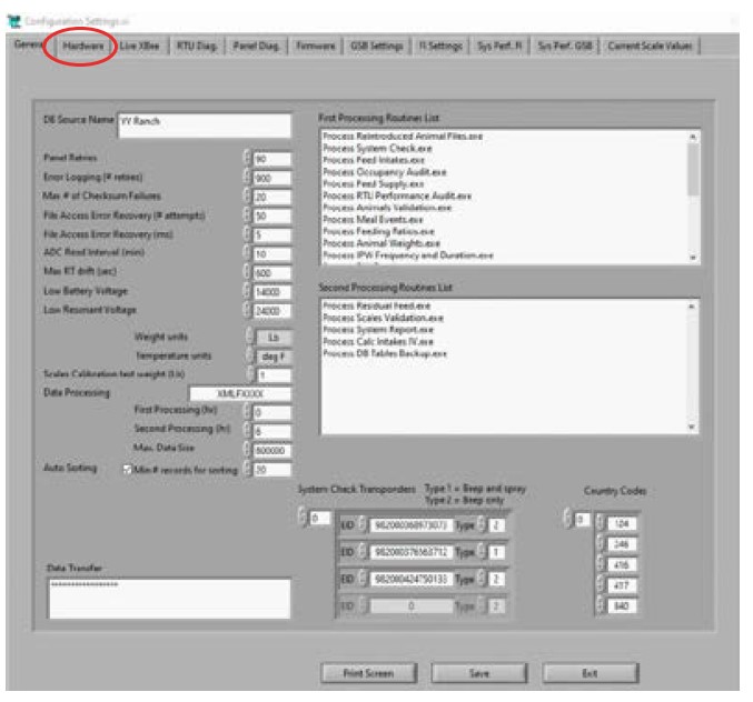
Configuration Settings page.
5. With the panel(s) online and connected to the data hub, the address number(s) should show up in the “Active Panels” list. Note the positioning of each panel on the side of the layout drawing and its address as it is important to have them configured correctly. (i.e., if the first panel has positions 1-4 in pen 1 and 5-8 in pen 2, the second panel has positions 9-12 in pen 3 and 13-16 in pen 4, the software must reflect that to collect accurate data – see below for example).
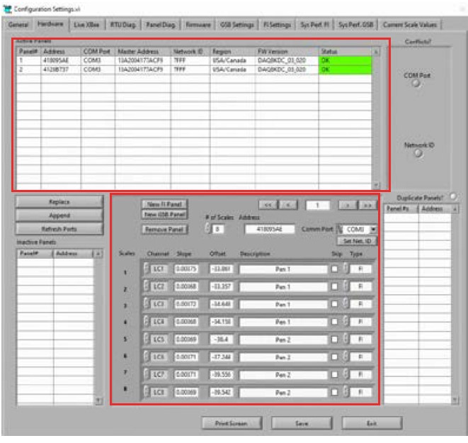
Hardware page. The Active Panels section has been highlighted, along with the section for filling in panel configuration details (e.g. pen description).
6. If the “Inactive Panels” list is empty, you can select the first panel on your Active Panel list and click the “Append” icon in the center left of the Hardware page. Do this with all the panels listed in the site layout drawing.
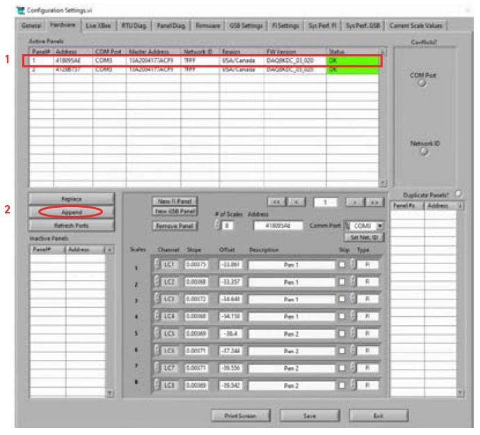
Hardware Page. Steps to “Append” panels are highlighted.
7. If the “Inactive Panels” list is already populated with the correct number of panels that you installed, you can select the first panel out of the Inactive Panels list and the first panel in the Active Panels list that matches your earlier recorded list and click the “Replace” icon in the center left of the Hardware page.
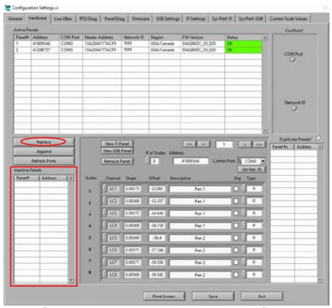
Hardware page. “Inactive Panel” section is highlighted along with the “Replace” button. Panels that show up in this section will be replaced by the active panels with addresses that match those installed.
8. After you have successfully added the panels you should see the panel numbers displayed that match the list of installed panels. You can then go through each panel in the “Active Panel” list and type in the correct pen information for each scale. Remember, the lowest numbered position always corresponds with the lowest lettered channel on the DAQ panel. (i.e., Panel #1: 1-8=A-H, Panel #2: 9-16=A-H).
9. Once all the scales on all the panels have been labelled correctly, make sure to save your changes with the icon in the bottom of the window. You will be prompted to enter your username and password each time you save changes to the system. It is preferred that you also leave a brief note detailing the changes you have made at this time.
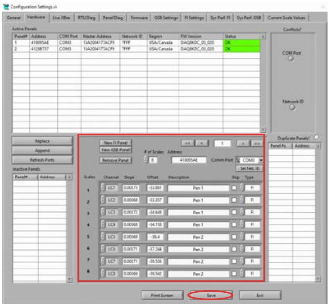
Hardware page. The section for pen information has been highlighted. This section must be filled in to accurately reflect the pen that each channel on the DAQ panel is associated with.
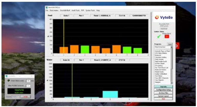
10. Once your changes have been saved, exit out of the Configuration window, and restart the software. You may need to use the task manager to close out the software. Once the DAQ software has restarted the red bars on the dashboard should turn white and there should be a green checkmark displayed in the top left corner when communication had been established.
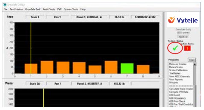
DAQ Dashboard home page. “System Status” is circled. If System Status does not display a checkmark the system is “In Error”.
11. If the bars are still red, check the following:
a. There may be a power issue in the field. Check the green power and orange DAQ status lights of all your panels in the field. Open their covers and make sure that all the green channel status lights are flashing as well as the Radio and GPS lights.
b. If power is okay, open the “Configuration Setup” window and check the status of the panels in the active panels list. They should all read “OKAY” in green. If they are listed in the “Inactive Panels” list then double check the antenna connection, USB connection, and the power lights on the data hub. If the bars are still red, contact your Field Service Coordinator for assistance.
5.5.1 ADDING TEST WANDS
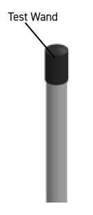
The Vytelle SENSE system is equipped with a ‘beep wand’ or test wand which will force the system to emit an audible beep to verify that the system is reading an RFID. This wand is used to complete routine system calibrations.
1. Locate the customer toolkit that was supplied with the shipment and obtain the test wand(s).
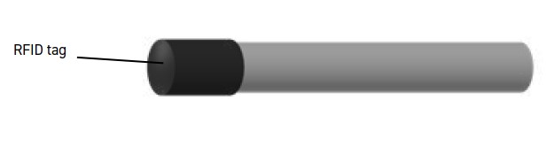
Test wand supplied with customer toolkit.
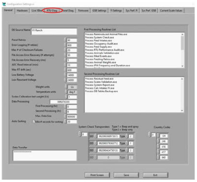
2. Open the “Configuration Setup” window and enter the test wand number found on the wand label and test wand type (beep wands are Type 2) in the lower right hand of the window. Save your changes with your user credentials.
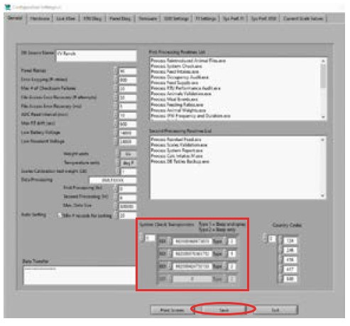
Configuration Settings page. The highlighted area is used to enter the information for new test wands.
3. Close the “Configuration Settings” window and open the “Read Write Spray Tables” program located in the “System Tools” drop down at the top of the DAQ dashboard.
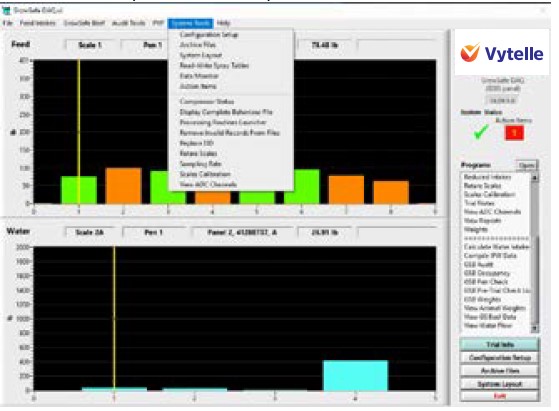
DAQ Dashboard home page. Steps to navigate to the Read-Write Spray Tables process are highlighted.
4. Select all your panels and click the “Write” icon. Wait for it to finish and the hit “Read” to make sure the panels have your test wand numbers stored on them.
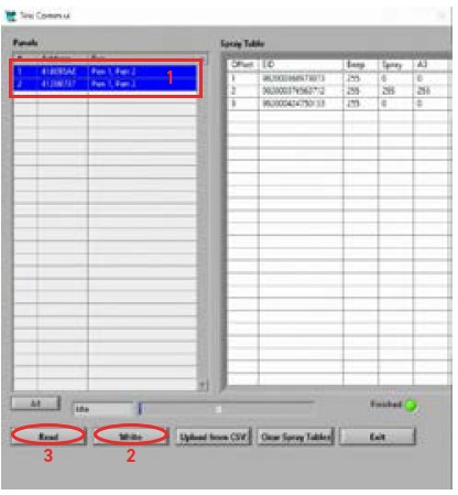
Read-Write Spray Tables page. Steps to associate new test wands with the installed DAQ panels are highlighted and numbered.
5.5.2 TUNING ANTENNAS & CALIBRATION
Tuning is done to automatically set the resonate voltage of the antenna to optimise RFID tag reads. Tuning is performed after the instillation of a new RTU. Calibration is used to ensure that the scales in the RTU’s are functioning correctly. Calibrations only need to be performed after the installation of a new RTU or on the entire system prior to the customer starting a trial. Taring is performed after calibration to set the zero-point displayed on the DAQ software.
As part of an installation, all scales will be calibrated and tared.
1. Open the “Configuration Setup” window and select the “RTU Diag” tab at the top center of the window.
Configuration Settings page.
2. Select your panel in the top left of the window and then click “Tune All” the process will work through all the scales individually. You can follow the process along by watching the number in the V Res column. When the scale antenna is tuning it will display “65553” when the tuning has been completed successfully the number displayed should be between 1100-1300. If the number is lower than 1000, inspect the pigtail and antenna connections on the position in question.
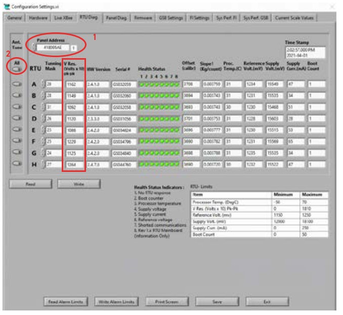
RTU Diag page. Steps to tune the scales associated with each DAQ panel are highlighted and numbered. V Res column is also highlighted.
After this process is completed for all the panels, you will need to physically calibrate each scale. The steps for a calibration should be performed in swift order.
3. Retrieve the 50 lb calibration weight that was shipped with the equipment.
4. Starting at the first scale, place the certified weight on to the floor of the trough and wait for approximately two seconds for the system to level.
5. WITHOUT TOUCHING THE TROUGH, hold the test wand in front of you such that it is positioned in the center of the trough with the black tip towards the trough floor and allow the system to beep fifteen times.
6. Repeat this process on all scales in the system, calibrate all nodes on the system in sequential order, starting at node 1 and moving on to node 2, node 3, etc.
IMPORTANT: If you do not have the user credentials to make system changes or you are having technical difficulties, please contact your Field Service Coordinator to have the following tasks completed. Once the calibrations have been completed note the time and weight on the “Trial Notes” program located on the DAQ Dashboard and notify your Field Service Coordinator to have the calibrations checked.
5.5.3 VERIFYING CALIBRATIONS & TARING
You will need to restart the DAQ software to get the system to pull the most recent data from the panels. If you have done your calibration within ten minutes of trying to check them, you will likely need to perform this task. Then you need to open the DAQ file explorer located in the task bar and copy the “Configuration” folder. Paste the copy of it inside the “Saved Configuration” folder. Once your configuration has been saved, you can close the file explorer. Open the “Calibrate Scales” program located in the right-hand program list.
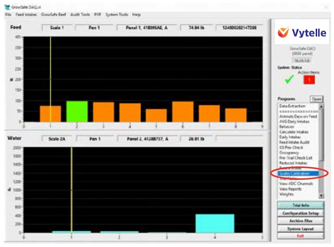
DAQ Dashboard home page.
The program will prompt you for your user credentials and a description of what you are calibrating. Once you have entered this you can begin checking calibrations.
1. Select FI as the “System Type” and enter 50 lb in the weight setting.
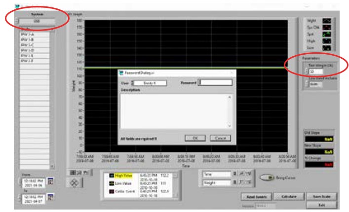
Scales Calibration page. Once credentials have been accepted, select FI as system type and enter ‘50’ in the Test Weight section.
2. Select the first scale from the list on the left-hand side of the window and work down from there.
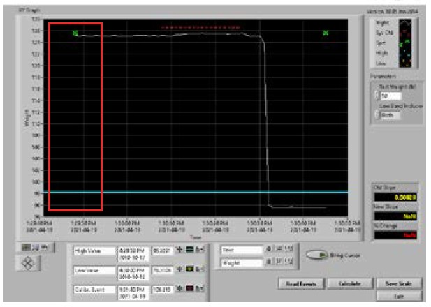
3. Once you select a scale you should be see the calibration you performed displayed on the graph. The graph should look clean with a clear rise in weight when the calibration was happening, a good leveling off during the calibrations, and a nice even baseline after the calibration is completed. See below for examples of acceptable and unacceptable calibrations.
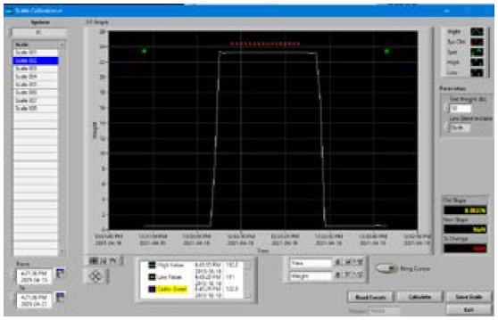
Visual of a clean calibration. Calibration has a clear rise in weight and an even baseline before and after the calibration.
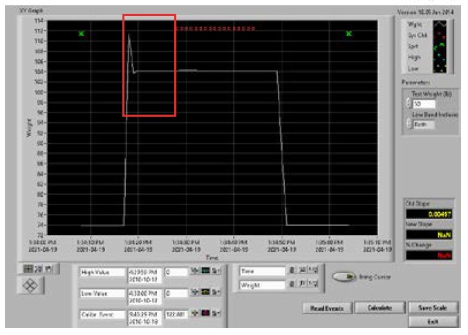
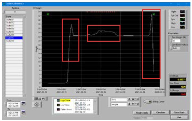
Visual of an acceptable calibration. The spike visible to the left suggests that the trough was briefly leaned on while the test weight was being placed into the trough, which ideally should be avoided, but in this case the calibration was not compromised since the scale was given time to level out before inserting the test wand to calibrate.
Visual of an unacceptable calibration that will have to be re-done. The left baseline is missing from the calibration, suggesting that the test wand was inserted into the trough too late after the test weight was placed in the trough.
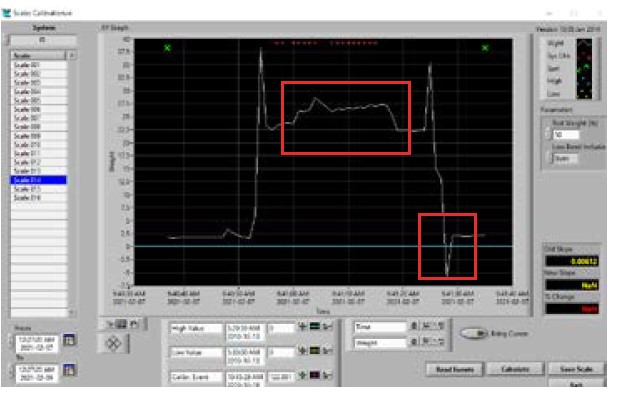
Visual of an unacceptable calibration that will have to be re-done. The right baseline is missing which suggests that the test weight was removed too late after the test wand. The spikes at each end suggest that the trough was contacted while taking the test weight in and out of the trough, which is okay, but the bump in the middle of the calibration suggests that the trough may have been contacted while the test wand was beeping the system.
Visual of an unacceptable calibration that will have to be re-done. The bumps in the middle of the calibration suggest contact or movement of the trough during the calibration and the negative spike on the right baseline suggests that there may be problems with the node’s RTU. Recalibration should be attempted and if this does not result in a better calibration, troubleshoot the node with help from Technical Support.
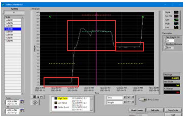
Visual of an unacceptable calibration that will have to be re-done. The calibration itself was not clean, suggesting contact or shifting of the trough during calibration, but the more concerning issue is that the baselines do not match up on the left and right sides. Recalibrate and if this does not fix the issue, troubleshoot with Technical Support.
4. If the calibration is acceptable, click the “Bring Cursor” icon and make sure the purple line is located between the calibration events, click “Calculate” and then “Save”. Repeat this on all calibrations performed.
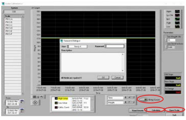
Scales Calibration page. Relevant buttons for navigating scale calibrations are highlighted.
IMPORTANT: Only click “Save” one time. Multiple clicks of the “Save” button with exponentially change the slope and the calibration will have to be re-done.
6. GENERAL INSTALLATION TROUBLESHOOTING
6.1 NO AUDIBLE BEEP WITH TEST WAND
First, confirm that the test wand was added to the panel correctly. At the Vytelle computer, open the “Configuration Setup” window and confirm the test wand number listed in the system matches the number of the test wand you intend to use. Save any of your changes with your user credentials. If the test wand number was entered correctly, sometimes re-writing and re-reading spray tables will fix the error. Accomplish this by following these steps:
1. Close the “Configuration Setup” window and open the “Read Write Spray Tables” program located in the “System Tools” drop down at the top of the DAQ dashboard.
2. Select all your panels and click the “Write” icon. Wait for it to finish and then hit “Read” to make sure the panels have your test wand numbers stored on them.
3. Test the test wands on the system. If all nodes on a particular DAQ panel do not beep, but the status light at the bottom of the DAQ is flashing to indicate the test wand is being read (when the wand is tested) AND the test wand is being registered on the Vytelle computer; the component of the DAQ panel that emits the sound, the beeper, likely needs to be unplugged and plugged back in or replaced entirely.
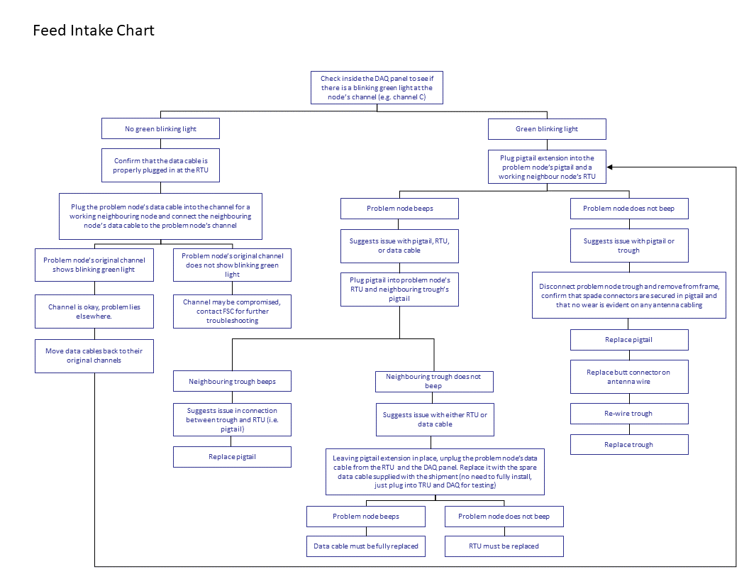
If the problem is with one or more nodes individually, refer to the troubleshooting flow chart in Appendix I.
6.2 CALIBRATION BASELINE DOES NOT RETURN TO ZERO OR IS NOT CLEAN
This is usually the result of rubbing between the trough and the Feed Intake Node frame at the affected nodes. Check to confirm that the trough is not hung up on the frame somewhere and that the trough is sitting correctly on the RTU load bars. A few common questions to work through:
• Am I accidentally leaning on the trough or contacting it as I am calibrating? If you must lean on the edge of the trough to put the calibration weight into the trough or to pull it out of the trough, that is okay, but if this is the case, you must wait two seconds to start beeping the system after you have placed the weight, and you should wait two seconds to remove the weight after you are finished beeping the system. This will prevent you from compromising the calibration baseline. You should not be contacting the trough at any point during the insertion of the beep wand or the beeping of the system.
• Is the trough misshapen because of shipping? If the trough shows signs of minor bending or bowing causing the trough to rub on the spill protector mounts, you may be able to force it back closer to its regular shape using a combination of pressure and heat. Leaving the trough installed in the frame overnight with a weight in it may also help it to settle into the proper shape.
• Does the calibration look cleaner if I swap the trough at the affected node with a different trough? Sometimes minor differences in the troughs can contribute to rubbing and this might be an easy fix.
• Are the frame arms level? Use a spirit level to confirm that the arms of the frame that hold the RTU load bars are level.
• Are the RTU load bars installed at an angle by mistake? Remove the trough at the affected node, loosen the bolts that mount the RTU load bars to the frame, and re-install the bolts ensuring that the load bars do not twist or lean as the bolts are tightened.
• Is the spill protector adjusted correctly? Make sure the spill protector is adjusted so that it does not contact the trough but is also not too high that it interferes with the feed truck or wagon. The bottom bolt on the bracket can be loosened to adjust the deflector to the correct position.
• Is the wind deflector touching the trough? Make sure the wind deflector is not leaning against the trough at all. The full weight of the deflector should be supported by the deflector brackets on the frame.
• Is the trough contacting the ground or an unsecured data cable or RTU cabling? Each of these contact points can contribute to noisy calibrations. Ensure all cables are properly secured to the frame and remove any potential obstacles below or around the trough that might interfere with its ability to sit freely on the load bars.
• Does the RTU need to be replaced? Have a discussion with the site’s Vytelle Technical Support Representative and ask them whether the calibration might indicate that the RTU is malfunctioning. If this is the case, the RTU may need to be replaced.
6.3 DAQ PANEL DOES NOT DISPLAY CORRECT LIGHTS
6.3.1 DAQ PANEL WILL NOT POWER ON
Confirm the panel has adequate power and is plugged in and have a qualified person verify the power to the DAQ panel is functional. If the power to the power supply has been verified and the panel does not power up, unplug power from the panel, remove and inspect the 20 mm 6 AMP glass tube fuse from the DAQ panel. If the fuse has been compromised, unplug all the data cables from the DAQ panel (being sure they are labelled to be plugged into the correct channel after troubleshooting is complete).
With the new fuse installed and the power supply plugged in, start plugging in the cables one at a time. Make sure to wait until their respective indicator light blinks green before plugging in the next cable. If the fuse blows again while you are plugging in the data cables, stop and fully inspect the specific cable that caused the fuse to blow for damage. Likely the cable has been damaged somewhere along its length and is creating a short, meaning the cable will have to be replaced with the supplied spare.
Repeat the above process until all data cables are plugged back into their respective channels and the panel remains powered on. Take care not to mix up the cables. If the DAQ panel fuse still blows after the data cable is replaced on the affected node, the RTU may need to be replaced.
6.3.2 NO GPS OR RADIO LIGHTS ON THE DAQ PANEL
Whenever the DAQ panel’s orange status light is not flashing or the GPS and radio lights inside the panel are not illuminated, the DAQ panel is not transmitting data.
Confirm that the GPS and radio antenna have not been damaged on top of the DAQ panel. Disconnect both antennas and then reconnect them. Cycle the DAQ panel power (i.e., unplug the power chord, wait for 30 seconds, and then plug the power chord back into the DAQ panel) and wait for the GPS, radio, and panel status lights to turn on (orange status light flashes every 0.5 seconds). It may take up to 5 minutes to establish a GPS connection.
If the lights do not come on there is a chance that the building’s roof that houses the system is made of a material that is blocking the communication and a stronger antenna may be required (contact your Field Service Coordinator for further instruction). Otherwise, the panel should be replaced.
6.3.3 DAQ SOFTWARE IS NOT RECEIVING DATA FROM DAQ PANEL(S)
Confirm that the DAQ panels are transmitting (i.e., the DAQ panel’s orange status light is blinking on a 0.5 second interval). Verify that the data hub is connected to the Vytelle computer and that it displays a green power light at the bottom. If no power light is visible, the data hub may need to be plugged into a different USB port. Ensure the data hub’s antenna is secured tightly.
If you have long-range Yagi antennas installed, ensure that they are correctly aimed at each other. There is a possibility that the line of sight from the DAQ panel to the data hub has been obstructed and the Yagi antenna may need to be mounted at a higher elevation.
If you are still having communication issues, contact your Field Service Coordinator for further troubleshooting
6.3.4 NO BLINKING INDICATOR LIGHT AT ONE OR MORE CHANNELS
Troubleshoot following the flow chart in Appendix I.
7. CUSTOMER TRAINING POINTS
7.1 FEED INTAKE NODES
System components starting roughly in order of troubleshooting.
Wind deflector: (show removal and re-installation)
• Stops wind from buffeting bunk therefore providing a cleaner weight reading from the load cells in the load bars.
• Helps prevent feed build up under the troughs.
Spill deflector: (show removal, re-installation, and adjustment)
• Stops feed from building up on top of and between bunks.
• Helps prevent build up of feed on and around load bars.
Appropriate time to mention cleaning of the system:
• Make sure feed does not build up excessively around the system.
• Generally, customers only need to clean up around the system before trials or as feed builds up.
• Suggest the customer keep a regular cleaning schedule for their system. They can vary the schedule to accommodate things like seasonal weather or usage.
• Make sure to clean up around/under load bars or it can result in noisy reading and or incorrect weight readings.
• Keeping the system clean usually helps prevent vermin from moving in and eating system electrical components. Wires are coated in a rodent resistant insulation and a stainless-steel loom, but this only prevents damage to a point. Antenna: (explain replacement of antenna wire and spade connectors)
• Located under rim of bunk and secured with foam backer rod.
• 14AWG stranded wire.
• Two complete wraps (not a twisted pair).
• Can be rewired (remove foam & reinstall 14AWG stranded wire mentioned earlier).
• Note: when replacing antenna wire that the butt connector that is factory installed is not necessary when replacing the wire. It is part of the procedure used at the factory to expedite the install. Having the complete two wraps around the trough lip is the most critical part of the antenna wire replacement.
• When crimping new spade connectors onto the antenna wire, ensure that the insulation is not pinched in between the connector and copper wire as this could impede the antenna’s functionality.
• RTU box uses antenna to charge and then read the EID tag number.
Trough: (show install removal & dumping technique)
• Unplug the pigtail before removal! This is the single most replaced component on any Feed Intake Node and damage to the component is completely avoided by ensuring the pigtail is unplugged before attempting to remove the trough.
• Show the customer where to look/feel for a correctly seated trough (load bar sitting correctly in the groves on the trough).
• Have the customer and/or person who is responsible for maintaining the system to remove and reinstall the trough.
• Holds approx. 400lbs (180kg) depending on ration density. Trough will go into error over 500lbs.
• Very durable.
• Should not have anything rubbing on bunk when in position or it will negatively affect the weight reading.
• Always test the trough with the test wand after any service or cleaning is performed to make sure you still have good read range.
Pigtail: (show replacement, cam-lock connect and disconnect)
• Connects the antenna to the RTU box.
• Customer must make sure pigtail is disconnected before the bunk is removed from the frame (we provide extras because it does happen from time to time).
• Make sure cam-lock connector is fully engaged.
• Show spade connectors, replacement method, connection requirements (orientation or placement of the spade connectors does not matter).
• Talk about pigtail extension tool and how to use when troubleshooting EID tag reading issues in troughs full of food.
RTU: complete scale, EID, and weight processor.
• RTU load bars: (show components/install & removal)
• Load cells are what weigh the feed, accurate to 1 gram.
• Show hardware connection locations to customer for removal and replacement.
• Ensure that cables are routed correctly on the system to prevent cables from rubbing on bunk or accessible to the cattle/vermin (must use cable ties).
• RTU box:
• The cells working in pairs in the load bars measures weight of feed in bunk.
• RTU box, collects weight data from scales and RFID data from antenna and sends it to the DAQ Panel.
• New powder coated; aluminum extruded case helps block out RF noise.
• Do not pressure wash the RTU box directly when cleaning the system
Frame and support brackets:
• Bolted together and anchored to the ground in four
spots (five spots on end positions where support brackets are installed).
• Holds RTU and trough.
• Vertical and horizontal neck bars are to be adjusted so that only one animal can access bunk at a time (need this to insure we can associate the eaten food to an animal).
• Frames are level. Must remain level to collect accurate weight data.
Data cable:
• Transfers weight and EID data to the DAQ panel.
• Same as a regular Ethernet cable (cat5 cable).
• Must be installed as shown on system to prevent cables from rubbing or animals from eating (must use cable ties).
DAQ Panel:
• A transmitter that gathers weight data from RTU boxes and sends it wirelessly to the data hub.
• The panel has two antennas located on the top of the unit. The longer of the two antennas is the unit’s radio antenna and the smaller of the two antennas is the GPS antenna. When replacing the panel make sure to replace the antennas.
• Has a simple 20mm 6amp glass tube fuse inside to protect the panel from shorts caused by damaged cables or other power issues. If the panel goes down check and make sure this fuse is not blown, if it is, there is probably another issue (e.g. a damaged cable. Shorts in the data cable caused by cattle, vermin, or other physical damage will cause this fuse to fail).
• The lights flashing above the individual channels indicate weather the channel is actively collecting data If it stops, it means the data is not being collected because the RTU is down or the cable is damaged/unplugged.
• The orange light flashing on a 0.5 second interval on the bottom of the panel indicates that the panel is collecting/transmitting data and functioning properly. This does not necessarily mean that data is being collected at the computer, but it does indicate that the panel is working. If the light is off or is not flashing on a 0.5 second interval, the panel is in error. This will also show up as red bars on the DAQ software.
• The solid green light indicates that we have GPS connection.
• If the panel goes down and the fuse is good, then the panel must be replaced. We send replacements and documents for the return of the faulty panel.
Power supply:
• Provides power to the entire system, scales and all.
• Waterproof and non-serviceable.
• If it fails, it must be replaced.
• Show connection to panel, as well as show connection to the power receptacle.
7.2 VYTELLE COMPUTER
Data hub:
• Collects data from DAQ8000 panels and makes it available to the computer where, during trials, it is stored and then sent to out and saved on our servers in Canada via the internet connection.
• Non-serviceable. if we have any issued, we replace the unit.
• Power light located on the bottom of the unit.
• Usually secured with hook and loop tape to the side of the computer of in a location to provide better communication with the DAQ panels.
• Must be connected to a USB 3.0 port on the computer. this port provides the correct amount of power to run the data hub.
Computer:
• Stores the data collected by the data hub.
• Has the DAQ software to interact with the system.
• Data displayed in the reports on the DAQ software is from the previous days data.
• Software uploads the days data to the Vytelle servers every morning at 12AM local time in Alberta.
Vytelle Servers:
• Stores data from our systems around the world.
7.3 SYSTEM TESTING AND MAINTENANCE
Customer Toolbox:
• Contains everything needed to service a Vytelle SENSE system.
• Replacement items should be requested from your TSR at Vytelle support when consumable items such as pigtails and spade connectors are used.
Test Wand:
• Kept in customer toolbox.
• Is used to test the read range (or distance at which tags can be read by the antenna).
• It has an EID tag installed in the cap that is programmed to make the system beep whenever it is read in one of the bunks.
• This shows that you have the correct read range in the bunk if it is beeping on a 1 second interval when held in the trough.
• If the beeps have long gaps in between, that indicates that the bunk in question is having “poor read range” issues or the bunk is not reading tags consistently and service is required.
Calibration:
• Is used to verify the scales are weighing correctly.
• Is only done after replacing a DAQ panel (i.e. calibrate all RTUs attached to that panel), replacing an individual RTU, or before starting a trial
• This can be done on individual scales, on a panel or pen basis, or on the system as a whole.
• A calibration weight has been supplied with the system. Only use this weight when calibrating the system.
• To calibrate, put the known weight (50 lb) into the bunk and then to insert the test wand into the same bunk, making sure not to touch or lean on the bunk, wait for 10-15 consistent beeps. Once you have had a consistent 10-15 beeps, you can remove the beep wand and the weight and repeat the process in every feed intake trough that needs calibration. Once all the bunks have had the weight installed for 10-15 beeps you can then note the time and weight used to calibrate on the trial notes software or in the pre-trial checklist.
Scale Tare/Re-Tare:
• Is used to set the zero point for the scale.
• This must be done after the scale calibration.
• This is done by emptying the bunks and leaving them empty for at least 10 minutes and then noting the time they were emptied on trial notes or pretrial checklist.
Troubleshooting:
• When troubleshooting EID read issues start from the antenna and work back to DAQ8000 panel.
• When troubleshooting weight issues start at the RTU and work back to the DAQ8000 panel.
• Rule out components one at a time (i.e. is the antenna good? Yes? Check the load bar assembly, is it working? Yes? Check the data cable, is it intact? Yes? Check the DAQ8000 panel, is it working? No? Replace the panel, etc.).
7.4 SOFTWARE
DAQ Dashboard:
• Displays live Feed Intake Node weights.
• Shows action items and system status in top right. Under the Vytelle logo.
• Has a list of programs.
• Trial info button on bottom right.
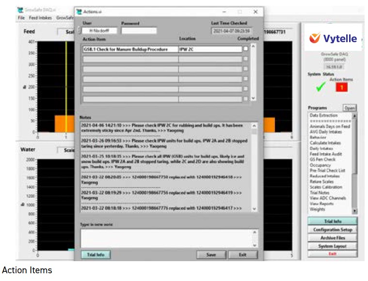
Action Items:
• Notification of required system service.
• Located under “System Tools.”
• Explain completion of action item (i.e. checking complete box/entering username, and
password).
• Action items are how we communicate for non-emergencies because it updates once a day at 6AM MST (when system uploads data to our servers).
• Support is going to/may have already sent a user access agreement form for usernames and passwords. We need a signed copy every time a person is added/removed from the system.
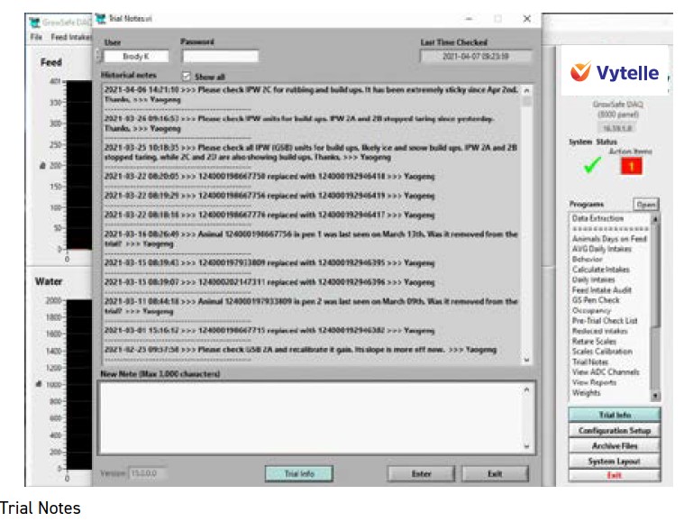
Trial Notes:
• Explain how action items are different from trial notes i.e. action items are notices of required service (change RTU’s, over/under feeding bunks, check rubbing, clean out bunks, etc.). Trial notes are for all other non-emergency communication i.e. calibration and tare information, tag change, or animal removal.
• Trial notes show the time the system was last checked by support in the top right-hand corner if it does not update when you’re running a trial, contact support.
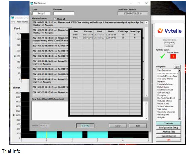
Trial Info:
• Click and hold to see your current trial information.
• Shows pen location, valid days vs done days.
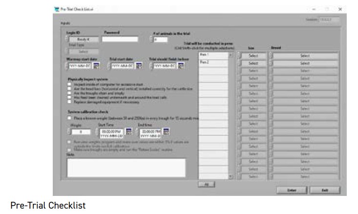
7.5 PRE-TRIAL CHECKLIST
Fill out a checklist with the customer and save as TEST in the notes section.
• To be done prior to starting a trial.
• Feed intake trials should last 70 days with a minimum valid day count of 35.
• RFI trials should last 50 days with a minimum valid day count of 35.
• If you are running both a Feed Intake Node and an In-Pen Weighing Position system, you have to go with the trial length of the Feed Intake Node system.
• Both trial types need to have 5 days in the beginning and 5 days at the end with one valid day for the trial to qualify.
• Show the action item PDF for filling out the pretrial checklist.
• Trials need to have a minimum 14-day warm-up. That is with animals on the system and EID tags in the animal’s ears. This is to make sure the system is working correctly, help figure out herd hierarchy, and make sure the animals are eating/drinking normally from the system.
• The pens on trial must be highlighted blue or they are not selected.
• If animals are removed from the trial during the trial. Let us know in trial notes so we can archive the file for that animal.
• If an EID tag is changed, let us know the old and new tag number so we can combine the info for those tags.
• Never re-use tags that have previously been registered on a Vytelle SENSE system, as this will merge previous animal data with new data.
• Plan for your first trial to go longer than average. There is a learning/adjustment period for customer and support while we work to get the system working accurately.
7.6 REPORTS TO CHECK DAILY
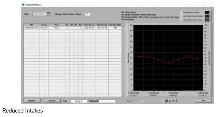
Reduced Intakes:
• Make sure to check a few days after beginning a trial. You will be able to easily find animals who are not adjusting to the system, animals with missing tags or animals that have been miss-penned.
• Explain the R indicators to the customer reduced intake, reduced intake for 2 days, 40% below pen average, no intake.
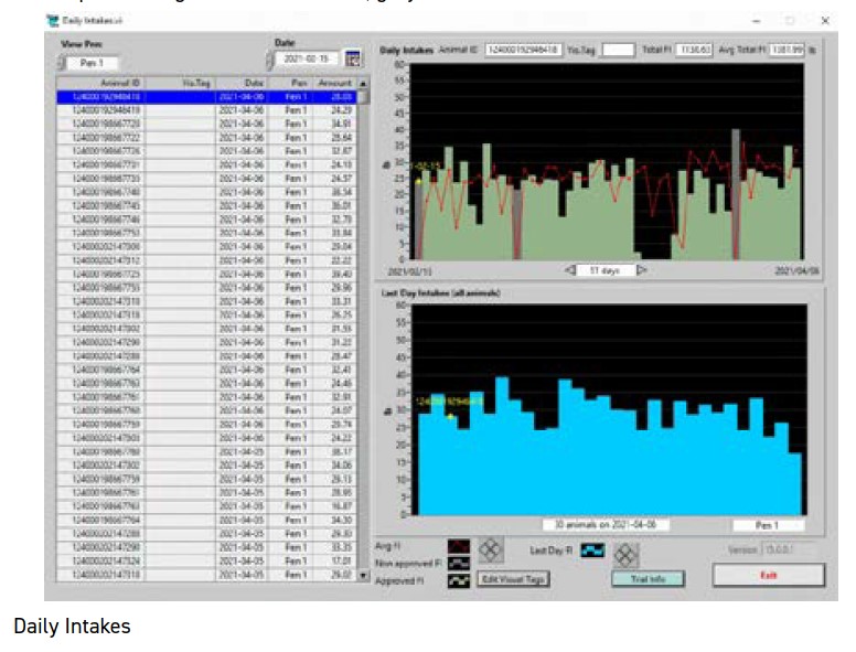
Daily Intakes:
• Monitor during warm up specially to make sure the number of tags match the number of animals on trial.
• Make sure the number of animals in the pens are correct.
• You can edit visual tags here (data is stored with the EID tag number and not the visual tag number).
• Graph colors: green = valid intakes, grey = invalid intakes (hardware related).
8. FINALIZING INSTALLATION
The final step in the installation of a Vytelle SENSE system is to complete the commissioning checklist, have it signed off by the customer, and sending it to you your Field Service Coordinator. This signifies that the instillation was successfully completed and approved by the customer. Make sure to check off all that applies to your specific installation. Add any important notes on any issues you encountered as well as anything that may yet need to be completed (e.g. fencing around the system etc.). Make sure to document the serial numbers of any spare equipment that was supplied for use by the TSRs during potential future troubleshooting (i.e. Parts in Trust).
If there were any significant changes to the site layout due to unforeseen circumstances, please notify your Field Service Coordinator to have the drawing updated to reflect the current site layout.
Optimized for print with Google Chrome browser.